Lighting fixture and method for operating same

a technology of fluorescent lamps and light fixtures, applied in the field of new operating modes of fluorescent lamps, can solve problems such as increasing the power efficiency of fluorescent lamps, and achieve the effect of avoiding voltage losses

Inactive Publication Date: 2013-08-27
DARRAS GILLES +1
View PDF18 Cites 0 Cited by
  • Summary
  • Abstract
  • Description
  • Claims
  • Application Information

AI Technical Summary

Benefits of technology

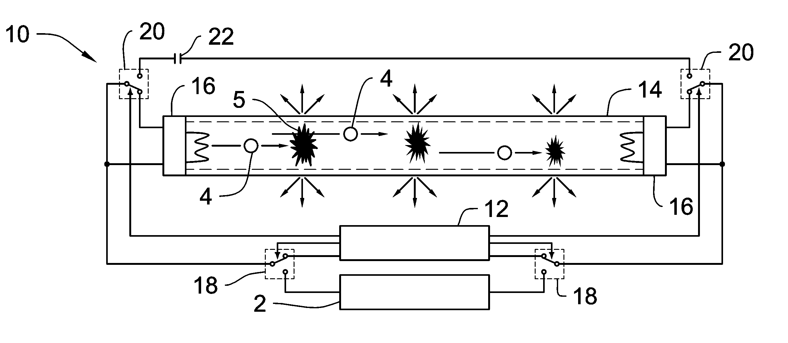
[0017]In a preferred implementation, the ballast generates pulses composed of perfectly alternate voltage amplitudes. The ballast is also able to control the timing of pulses as well as the dead times by using programmed algorithms. Another benefit can result in monitoring dead times between pulses from real time samplings of the current in the tube. Special coupling installed in tube's connections are controlled by the ballast to short cut cathode's filaments on right time, in order to cancel any current flow through it and so avoid losses of voltage. Ignition of conduction in the tube can profit of temporarily connecting a capacitor that seriously increases voltage at ends of every fluorescent tube and is disconnected as soon as the conduction establishes. The ballast modifies the current in the tube after the conduction happens in order to reduce the current in the capacitor to the minimum before disconnecting it.

Problems solved by technology

Obviously the objective is not to increase the power efficiency of fluorescent lamps.

Method used


Image

  • Lighting fixture and method for operating same
  • Lighting fixture and method for operating same
  • Lighting fixture and method for operating same

Examples


Embodiment Construction

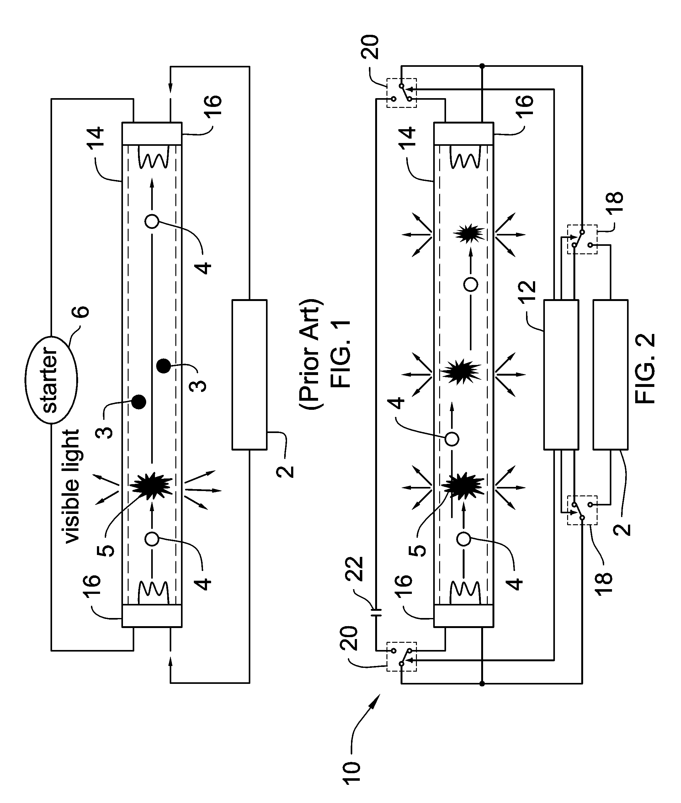
[0030]FIG. 1 in appendix represents the simplest shape of a magneto-inductive type ballast 2 in series with a fluorescent tube 14, in which the electric main voltage supplies the tube 1 with a frequency of 50 or 60 Hz. This kind of ballast, with possibly some minor evolutions, are mostly used in today luminaries. Although some manufacturers are seeking to market new electronic ballasts because luminaries equipped with such electronic ballasts have higher costs that significantly restrain a broad diffusion of these technologies.

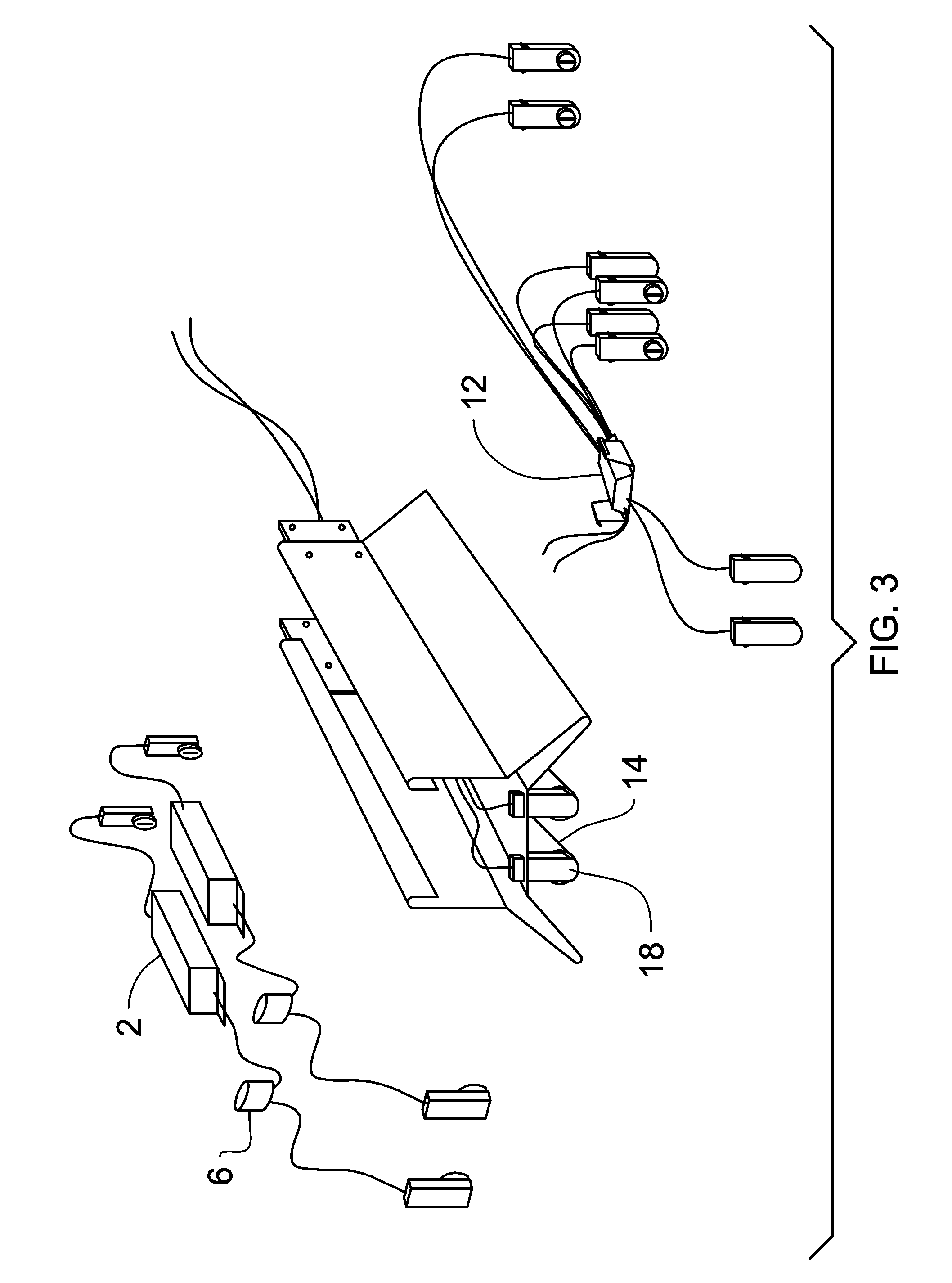
[0031]The present invention characterizes a new kind of electronic ballast different from existing systems by the fact that it is intended to replace the conventional magnetic ballast in existing luminaries without need of removing the original magnetic ballast when installing the ballast from the invention.

[0032]FIG. 2 schematically represents the action of the new ballast 12 designed with the invention 10. The operation of a fluorescent tube 14 equipped with...


PUM


Abstract

A ballast for fluorescent tubes and the use thereof for producing fluorescent tube lighting fixtures using a novel gas excitation mode in which light is generated by means of controlled pulses leading to an increased power efficiency, with a data collection and transmission functionality, are disclosed.

Description

CROSS-REFERENCE TO RELATED APPLICATION[0001]This application is an U.S. national phase application under 35 U.S.C. §371 based upon co-pending International Application No. PCT / IB2004 / 003819 filed on Oct. 19, 2004. Additionally, this U.S. national phase application claims the benefit of priority of co-pending International Application No. PCT / IB2004 / 003819 filed on Oct. 19, 2004, and Norway Application No. 20034700 filed on Oct. 21, 2003. The entire disclosures of the prior applications are incorporated herein by reference. The international application was published on May 19, 2005 under Publication No. WO 2005 / 046295.BACKGROUND OF THE INVENTION[0002]1. Field of the Invention[0003]This invention relates in general to fluorescent lighting luminaries and more particularly to a new operating mode of fluorescent tubes in a luminary.[0004]2. Description of the Prior Art[0005]A fluorescent tube is a discharge glass bulb whose inner side is covered with fluorescent layer that reacts by emi...

Claims


Application Information

Patent Timeline
Patent Type & Authority Patents(United States)
IPC IPC(8): H05B41/00H05B41/04H05B41/295H05B41/392
CPCH05B41/046H05B41/295H05B41/3927H05B41/00H05B41/04H05B41/30
Inventor DARRAS, GILLESMAILLACH, PASCAL
Owner DARRAS GILLES
Why Eureka
Try Eureka