Power management DC-DC converter and method for induction energy harvester

a technology of dc-dc converter and power management, applied in the field of power, can solve the problems of not allowing any energy to be harvested, take several minutes before there is sufficient energy, etc., and achieve the effect of avoiding the high cost of coils or inductor

Active Publication Date: 2012-11-13
TEXAS INSTR INC
View PDF7 Cites 0 Cited by
  • Summary
  • Abstract
  • Description
  • Claims
  • Application Information

AI Technical Summary

Benefits of technology

[0016]It is an object of the invention to provide a way to avoid the high cost of the coil or inductor usually required in a DC-DC converter utilized for conversion of the AC output generated by an induction energy harvester.
[0017]It is another object of the invention to provide an inductive energy harvesting device which is more efficient than those available in the prior art and which avoids voltage losses in rectifier diodes.
[0018]It is another object of the invention to provide an inductive energy harvesting device which is more efficient than those available in the prior art and which is capable of efficient harvesting of very low AC voltage levels produced by relative movement between a coil and a magnet thereof in a low-vibration-level environment.
[0019]It is another object of the invention to provide an inductive energy harvesting device which is more efficient and effective than those available in the prior art and which avoids voltage losses in rectifier diodes in prior art inductive energy harvesting devices and which is capable of more efficient harvesting of very low AC voltage levels produced by relative movement between a coil and a magnet thereof in a low-vibration-level environment than has been achievable in the prior art.

Problems solved by technology

Consequently, at low vibration levels it may take several minutes before there is sufficient energy to acquire a vibration spectra and transmit it.
Another shortcoming is that it does not allow any energy at all to be harvested at very low vibration levels (for example, when VDDCAP) because it does not develop enough voltage to adequately charge filter capacitor C0.

Method used


Image

  • Power management DC-DC converter and method for induction energy harvester
  • Power management DC-DC converter and method for induction energy harvester
  • Power management DC-DC converter and method for induction energy harvester

Examples


Embodiment Construction

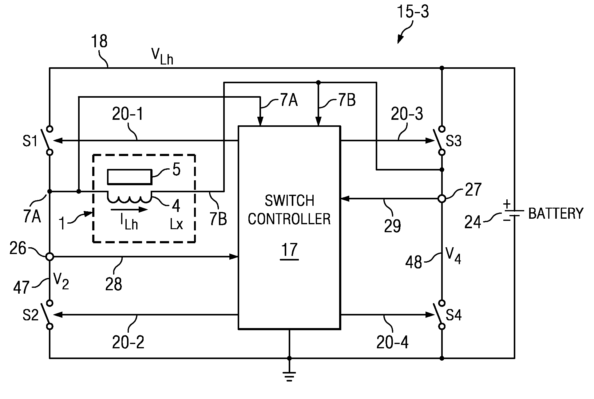
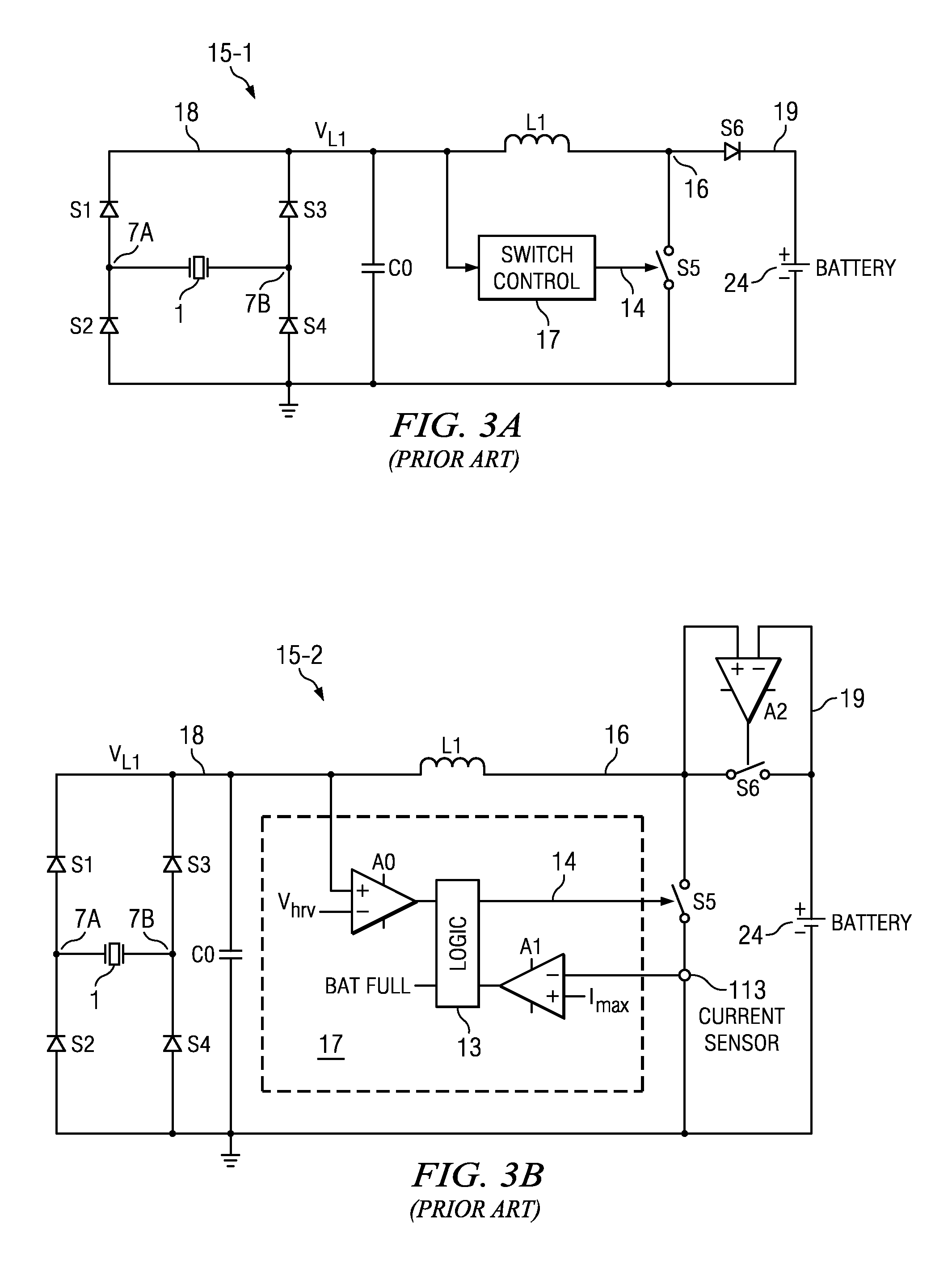
[0042]The first two previously mentioned problems of the system of Prior Art FIGS. 3A and 3B (i.e., the requirement of a large inductor in a DC-DC converter & loss of excessive voltage and power across passive rectifier diodes) can be solved by providing an active rectifier including synchronous switches in place of diodes S1,2,3,4 and also including a switch controller of the kind shown in FIGS. 4A and 4B.

[0043]Referring to FIG. 4A, power management system 15-3 includes switch S1 coupled between conductor 18 and terminal 7A of coil 4, also referred to as inductor 4. Terminal 7A of inductor 4 also is connected to a terminal of current sensor 26 and an input of switch controller 17. The output of current sensor 26 is connected by conductor 28 to another input of switch controller 17.

[0044]Switch S2 is coupled between another terminal 47 of current sensor 26 and ground. Similarly, switch S3 is coupled between conductor 18 and terminal 7B of inductor 4. Terminal 7B of inductor 4 is als...


PUM

PropertyMeasurementUnit
frequencyaaaaaaaaaa
switching frequencyaaaaaaaaaa

Abstract

A system for managing AC energy harvested from a harvesting device (1) including a coil (4) including switching circuitry (S1-S4) coupled between first (7A) and second (7B) terminals of the coil. The switching circuitry includes first (S1), second (S2), third (S1), and fourth (S4) switches. A switch controller (17) closes the second and fourth switches to allow build-up of current (ILh) in the coil, opens one of the second and fourth switches, and closes a corresponding one of the third and first switches in response to the built-up inductor current reaching a predetermined threshold value (Ihrv) to steer the built-up inductor current through the corresponding one of the third and first switches to a current-receiving device (24 and / or RL, CL).

Description

BACKGROUND OF THE INVENTION[0001]The present invention relates generally to use of induction type energy harvesters along with DC-DC converters, and more particularly to switching circuitry and techniques for using the inductance of the energy harvester both for inductive energy harvesting and for performing DC-DC conversion of the energy harvester output.[0002]The basic structure of an induction type vibration energy harvester 1 is shown in FIG. 1. It includes a mass m and associated coil or inductor 4 suspended on one end of a spring 2. The mass m and coil 4 move with velocity v relative to a magnet 5. The other end of spring 2 and magnet 5 are supported by a support 6. (The coil might be stationary with the magnet moving, or vice versa.). When coil 4 and associated mass m move with velocity v in the magnetic field, their kinetic energy Ek=(mv2) / 2 is transformed into potential energy in spring 2 which then is converted into electromagnetic energy ELh=eL=(LhILh2) / 2. The electromoti...

Claims


Application Information

Patent Timeline
Patent Type & Authority Patents(United States)
IPC IPC(8): B23K11/24H02B1/24
CPCH02M7/219
Inventor IVANOV, VADIM V.
Owner TEXAS INSTR INC
Why Eureka
Try Eureka