Vehicular marker lamp

a technology of marker lamps and lamps, applied in the field of vehicle marker lamps, can solve the problems of relative monotony and no novelty in the prior art lamps, and achieve the effects of novel appearance, enhanced red color intensity, and novel appearan

Inactive Publication Date: 2005-05-24
KOITO MFG CO LTD
View PDF7 Cites 31 Cited by
  • Summary
  • Abstract
  • Description
  • Claims
  • Application Information

AI Technical Summary

Benefits of technology

[0021]Thus, according to the present invention, the vehicular marker lamp of the present invention that is lit in red has a novel appearance when it is lit.
[0022]Further, in the vehicular marker lamp of the present invention, there is a difference in red color intensity between the direct light-emitting region and the indirect light-emitting region. Accordingly, it is possible to provide a lamp design that has various intensities of red color, and it is also possible to provide lamp that has a novel appearance even when the lamp is not lit.
[0023]In the above-described structure, the light source that emits light to the red transparent region can be one that emits red light. With this arrangement, the red transparent region appears to illuminate in red with an enhanced red color intensity. In this case, if the light source that emits light to the colorless transparent region is formed by one that emits red light, then the intensity of the red color increases further even in the colorless transparent region. On the other hand, if such a light source emits white light, the difference in the red color intensity between the red transparent region and the colorless transparent region becomes significant, and the contrast between those two regions can provide an even more novel appearance when the lamp is lit.
[0024]In the above-described structure, a second translucent member which is red and transparent can be provided between the direct light-emitting region and the first light source with the direct light-emitting region being set as a red transparent region. With this arrangement, when the lamp is lit, the red transparent region appears to illuminate in red with an enhanced color intensity. In this case, the second translucent member can be formed as a part of the translucent member, and this structure makes the lamp simple in structure.

Problems solved by technology

Accordingly, when the lamp is lit, it appears to illuminate in mere red, which is relatively monotonous.
Thus, the problem is that there is no novelty involved in lighting in the prior art lamps.

Method used


Image

  • Vehicular marker lamp
  • Vehicular marker lamp
  • Vehicular marker lamp

Examples


Embodiment Construction

[0034]Hereafter, embodiments of the present invention will be described with reference to the accompanying drawings.

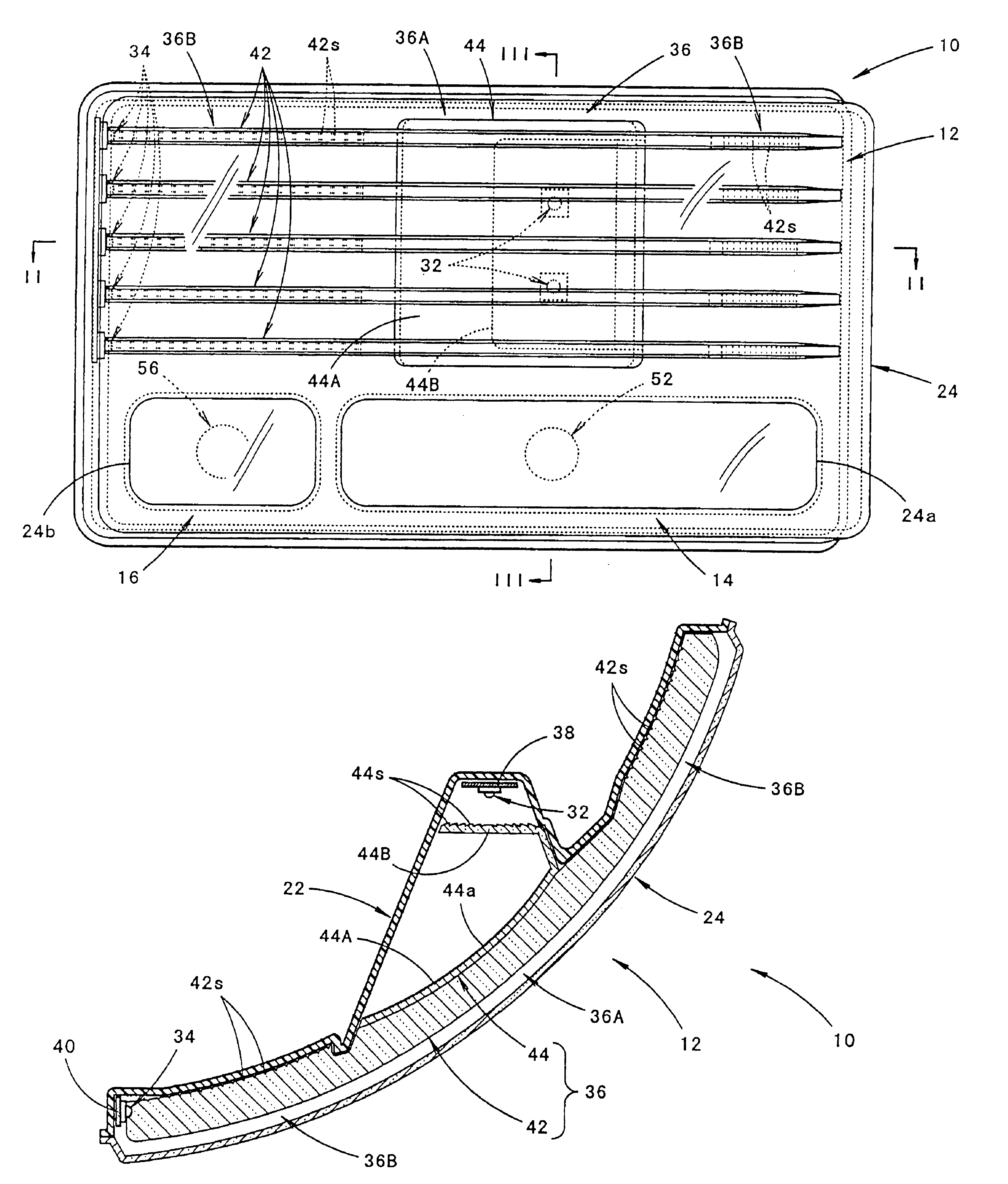
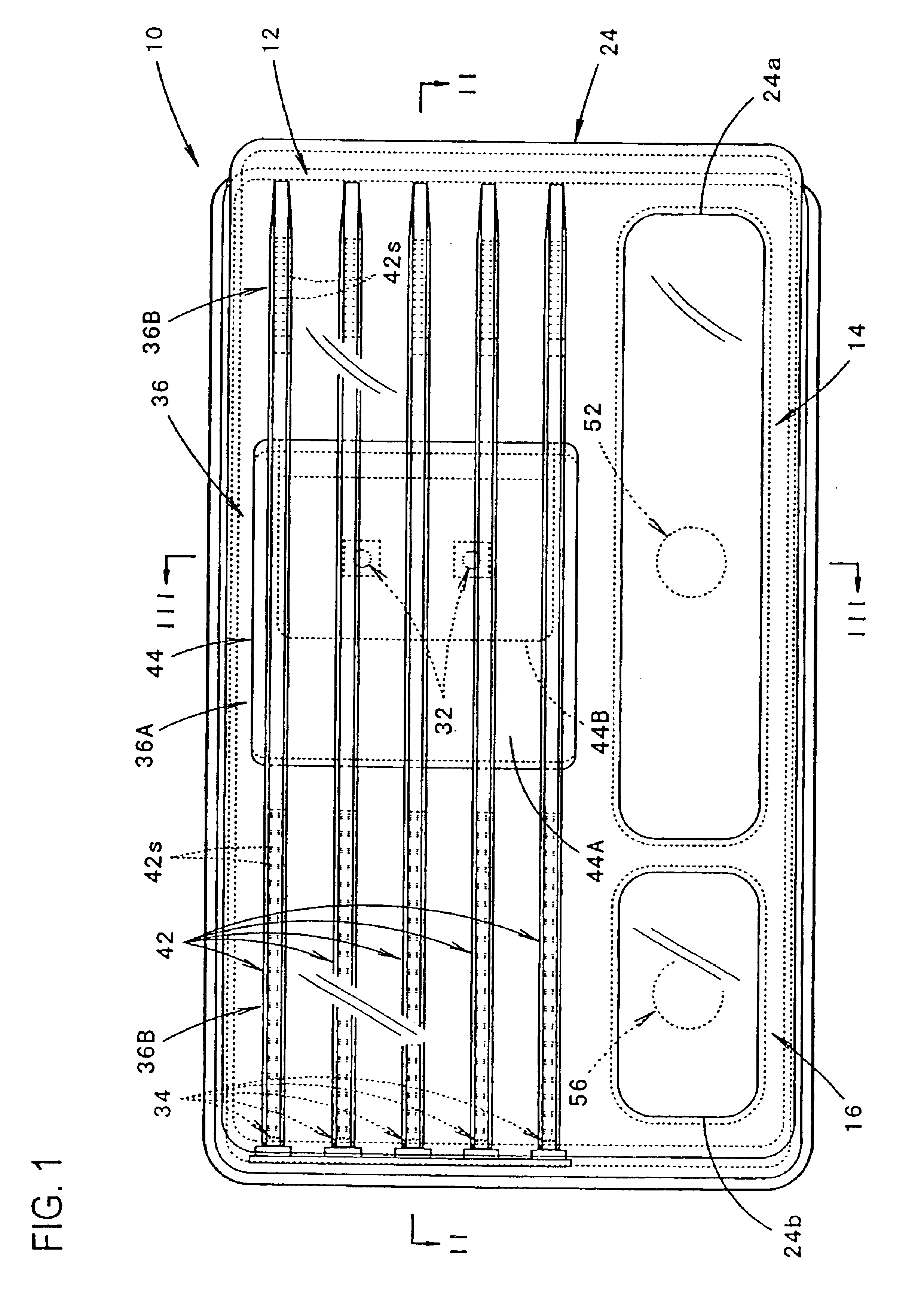
[0035]As shown in FIGS. 1 through 3, the vehicular marker lamp 10 of the shown embodiment of the present invention is a rear combination lamp mounted on the right rear end portion of a vehicle; and it includes a tail and stop lamp 12, a turn signal lamp 14, and a backup lamp 16. It should be noted that terms related to orientation, such as forward, rearward or the like, refers to orientation of the vehicular lamp 10, which is reverse to the orientation of the vehicle.

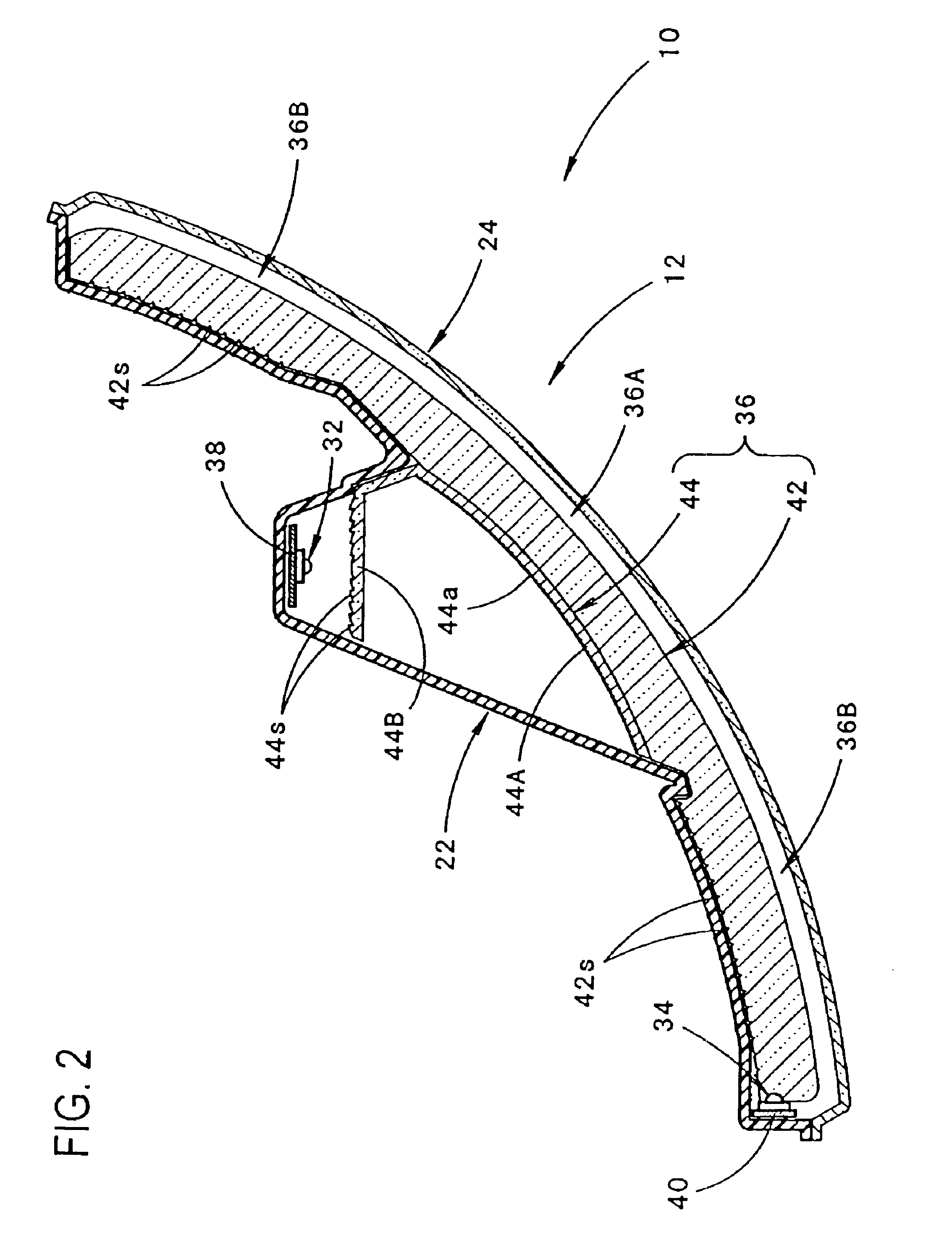
[0036]The vehicular lamp 10 has a substantially horizontally long rectangular profile when it is viewed, as seen from FIG. 1, from the front. As best seen from FIG. 2, a lamp body 22 and a translucent cover 24 attached to the front end opening of the lamp body 22 form a lamp chamber for the tail and stop lamp 12, a lamp chamber for the turn signal lamp 14, and a lamp chamber for the backup lamp 16 (see FIG...


PUM


Abstract

A vehicular marker lamp such as a tail and stop lamp, including a translucent member extending substantially along a translucent cover which is red and transparent with first light-emitting diodes in the back and second light-emitting diodes near the side end of the cover. The translucent member has a direct light-emitting region that transmits light, which is incident to the translucent member from the first light-emitting diodes, toward the front, and indirect light-emitting regions that internally reflect light, which is incident to the translucent member from the second light-emitting diodes, so as to emit such light toward the front. The direct light-emitting region is a red transparent region, and the indirect light-emitting regions are colorless transparent regions, thus allowing the appearances of the direct and indirect light-emitting regions to be significantly different from each other when the lamp is lit.

Description

BACKGROUND OF THE INVENTION[0001]1. Field of the Invention[0002]The present invention relates to a vehicular marker lamp that is be lit in red.[0003]2. Prior Art[0004]Generally, a vehicular marker lamp that is lit in red such as a tail and stop lamp and the like is equipped with a red and transparent translucent cover as disclosed in Japanese Patent Application Laid-Open (Kokai) No. 2000-195309. In the tail and stop lamp shown in Japanese Patent Application Laid-Open (Kokai) No. 2000-322905, a red and transparent translucent member is provided between a light source and a translucent cover.[0005]However, in these conventional vehicular marker lamps, the entire translucent cover or the entire translucent member is formed by a red and transparent member. Accordingly, when the lamp is lit, it appears to illuminate in mere red, which is relatively monotonous. Thus, the problem is that there is no novelty involved in lighting in the prior art lamps.SUMMARY OF THE INVENTION[0006]In view o...

Claims


Application Information

Patent Timeline
Patent Type & Authority Patents(United States)
IPC IPC(8): B60Q1/26F21S8/10F21W101/14F21Y101/02
CPCB60Q1/0058B60Q1/2607F21S48/2287F21S48/2237F21S48/2268F21S48/2212F21S48/215F21S43/14F21S43/26F21S43/237F21S43/245F21S43/247
Inventor YAMADA, KENJITERANISHI, YASUO
Owner KOITO MFG CO LTD
Why Eureka
Try Eureka