Adjustable locking mount and methods of use

a technology of locking mount and adjustable position, which is applied in the direction of couplings, instruments, machine supports, etc., can solve the problems of limited adjustment range of conventional adjustable mounts and may not hold the desired position, and achieve the effect of straightforward and robustness

Inactive Publication Date: 2005-05-24
TORNIER INC
View PDF32 Cites 29 Cited by
  • Summary
  • Abstract
  • Description
  • Claims
  • Application Information

AI Technical Summary

Benefits of technology

[0005]The invention provides an adjustable mount that permits a wide range of adjustment along or about multiple axes. The invention also provides an adjustable mount that makes possible a straightforward

Problems solved by technology

However, conventional adjustable mounts provide a limited range of adjustment.
Further, even upon

Method used


Image

  • Adjustable locking mount and methods of use
  • Adjustable locking mount and methods of use
  • Adjustable locking mount and methods of use

Examples


Embodiment Construction

[0036]Although the disclosure hereof is detailed and exact to enable those skilled in the art to practice the invention, the physical embodiments herein disclosed merely exemplify the invention that may be embodied in other specific structure. While the preferred embodiment has been described, the details may be changed without departing from the invention, which is defined by the claims.

I. The Adjustable Locking Mount System

[0037]A. System 1: Interior Hub Centrally Located with Respect to Mounting Surface

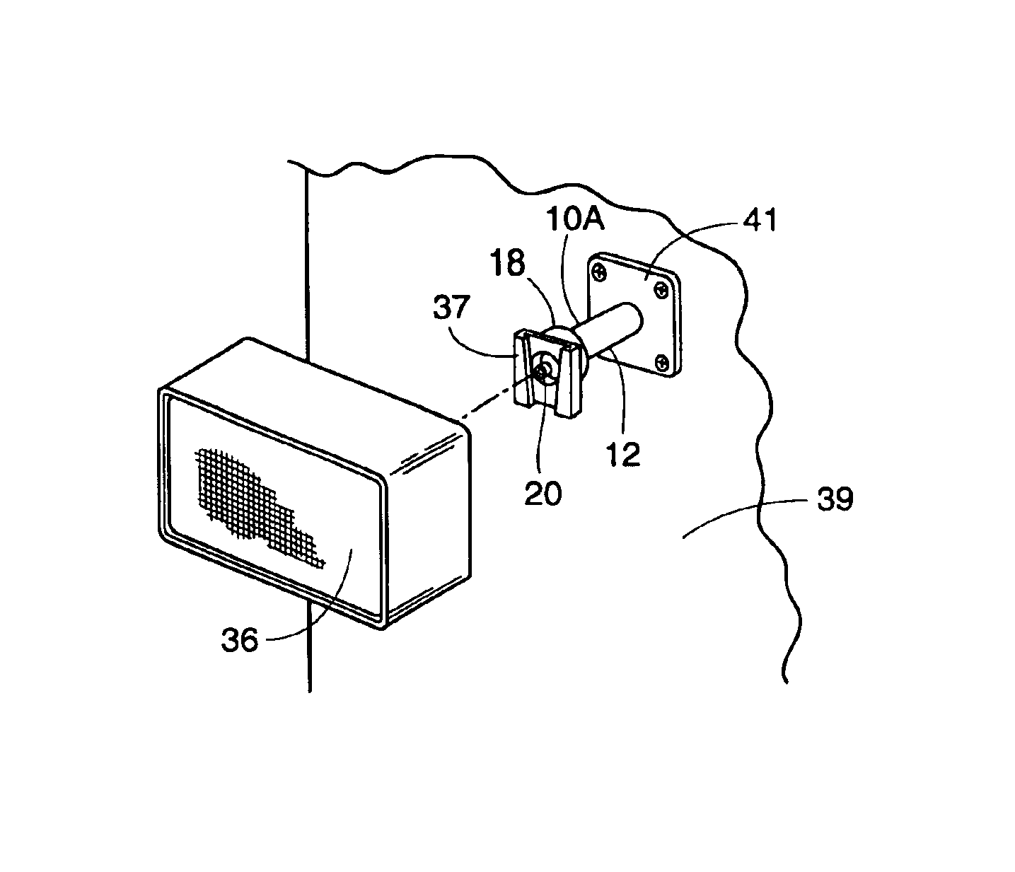
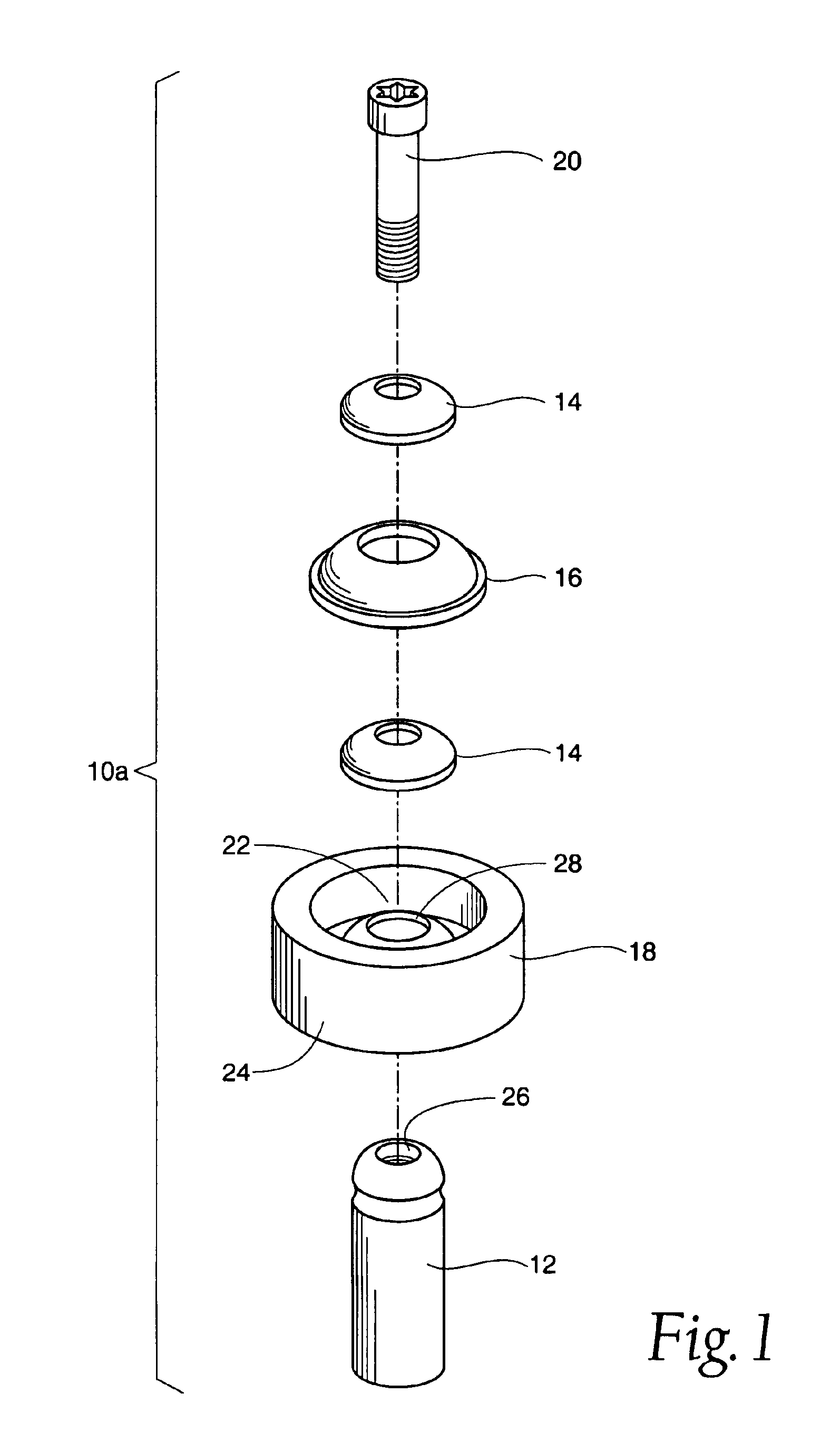
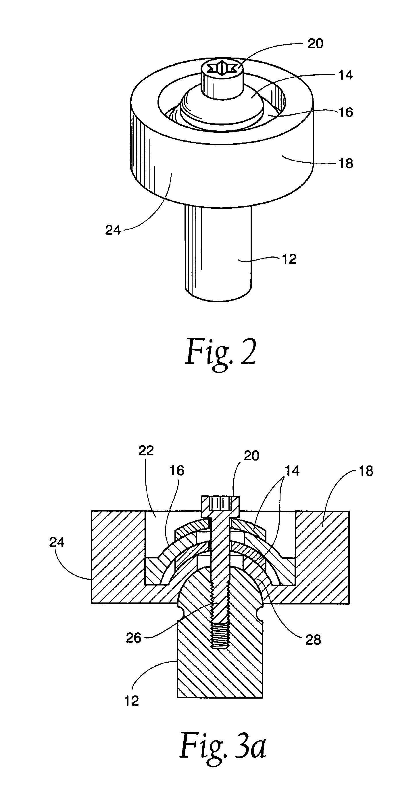
[0038]FIG. 1 shows the individual components of an adjustable locking mounting system 10A. FIGS. 2 and 3a illustrate the system 10A when assembled. As will be described in detail later, the system 10A permits adjustment in three directions or three degrees of freedom (rotational around axes x, y, and z, where the z-axis is represented by the axis of the pivot pin 12) (see FIGS. 4a-4e).

[0039]The system 10A comprises the pivot pin 12, at least one slip washer 14, at least one lock wa...


PUM


Abstract

An adjustable locking mount system permits rotation about at least one of x, y, and z axes. Methods provide for rotating and rocking the mount to obtain the desired position, fixing the mount in the desired position, and mounting an object onto the mount.

Description

RELATED APPLICATIONS[0001]This application is a divisional of U.S. application Ser. No. 10 / 041,707 filed 8 Jan. 2002 now U.S. Pat. No. 6,688,798, which claims the benefit of provisional U.S. Application Ser. No. 60 / 271,895 filed 27 Feb. 2001.FIELD OF THE INVENTION[0002]This invention generally relates to adjustable mounting devices and related methods.BACKGROUND OF THE INVENTION[0003]Adjustable mounting devices are commonly employed to mount one object or device onto another object, device, or structure. Typically, the position of the mount needs to be adjusted until the desired position is achieved. The desired position can then be secured by locking the device in the position, e.g., by tightening a screw.[0004]However, conventional adjustable mounts provide a limited range of adjustment. Further, even upon locking the device in a desired position, conventional mounts may not hold the desired position. This is especially true when force is exerted upon the mounted object, e.g., ham...

Claims


Application Information

Patent Timeline
IPC IPC(8): F16C11/10F16C11/04F16C11/06F16M11/14F16M11/02
CPCF16C11/0661F16C11/106F16M11/14F16M11/2078F16M2200/022Y10T403/32737Y10T403/32262Y10T403/32639Y10T403/32311Y10T403/32704Y10T403/7066Y10T16/95F16C2326/20
Inventor MCDEVITT, DENNIS
Owner TORNIER INC
Why Eureka
Try Eureka