Underground gas-driven drainage pump and gas-driven drainage method

A technology of gas drive and pump barrel, which is applied in the direction of mining fluid, earthwork drilling, wellbore/well components, etc. It can solve the problems of limited application range, eccentric wear of pipes and rods, and large versatility limitations, and achieve easy ground automation Control and management, energy saving and work efficiency are obvious, and the effect of high work reliability

Active Publication Date: 2020-12-04
YANGTZE UNIVERSITY
View PDF17 Cites 1 Cited by
  • Summary
  • Abstract
  • Description
  • Claims
  • Application Information

AI Technical Summary

Problems solved by technology

It has been proved through application practice that each technology has its advantages, but at the same time there are some defects. These technologies have limited versatility, and the outstanding problem is that they cannot better meet the large number of low-yield, low-energy and late-development needs on site.
The main manifestations are firstly that as the formation pressure and production decrease during development, technologies such as plunger drainage, gas lift valve gas lift and electric submersible pump drainage are no longer suitable for this development stage; High, such as jet pump drainage, etc.; third, rod pumps such as oil well pumps and screw pumps not only consume high energy consumption, but also have problems such as eccentric wear, breakage, and corrosion caused by pipe rods that have always plagued field applications; fourth, drainage The volume adjustment range is narrow and the use range is limited

Method used


Image

  • Underground gas-driven drainage pump and gas-driven drainage method
  • Underground gas-driven drainage pump and gas-driven drainage method
  • Underground gas-driven drainage pump and gas-driven drainage method

Examples


Embodiment Construction

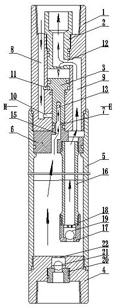
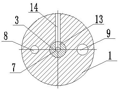
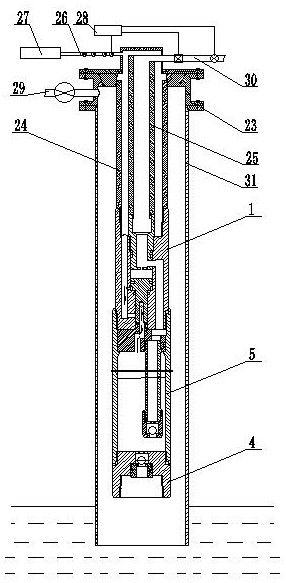
[0038] The downhole gas drive drainage pump includes a drainage pump casing 1, a pump barrel 5, an inner joint 2, a valve core 3, a lower joint 4 and a diverter block 6; A diverter block 6 is installed through the inner flange, and a drainage pump housing 1 is mounted on the top thread of the pump cylinder 5, and the drainage pump housing 1 cooperates with the inner flange to form an axial limit for the diverter block 6.

[0039] The drainage pump housing 1 is provided with a stepped center hole, the inner thread of the upper port of the center hole is equipped with an inner joint 2, the inner joint 2 is a barrel-shaped body, and the center of the inner joint 2 is provided with a stepped central hole. The bottom of the central hole of the inner joint 2 is constricted, which is used to transmit pressure to the bottom.

[0040]A spool 3 is installed in the center hole below the inner joint 2. The spool 3 is a T-shaped variable diameter body. The center of the lower end of the sp...


PUM


Abstract

The invention relates to an underground gas-driven drainage pump and a gas-driven drainage method, and belongs to the technical field of oil and gas exploitation underground tools. A flow dividing block is arranged in a pump cylinder; a drainage pump shell is arranged at one end of the pump cylinder in a threaded mode, and a lower joint is arranged at the other end of the pump cylinder in a threaded mode; a stepped center hole is formed in the drainage pump shell, an inner joint is arranged in an upper port of the center hole in a threaded mode, and a valve element is arranged in the center hole below the inner joint; and a gas injection flow channel is axially formed in the position, on one side of the inner joint and the valve element, of the drainage pump shell, and a lifting flow channel is axially formed in the position, on the other side of the inner joint and the valve element, of the drainage pump shell. The drainage pump achieves lifting by directly transmitting ground pressure energy to liquid in a closed space, and has the characteristics of being high in lifting efficiency and low in energy consumption. Compared with the prior art, the underground gas-driven drainage pump has the advantages that the working reliability is high, the problem of gas locking in the working process is avoided, meanwhile, back pressure is not generated to the stratum, and the undergroundgas-driven drainage pump is particularly suitable for oil extraction of low-energy and low-yield wells.

Description

technical field [0001] The invention relates to a downhole gas drive drainage pump and a gas drive drainage method, belonging to the technical field of downhole tools for oil and gas exploitation. Background technique [0002] During the production process of natural gas wells, formation water is often produced. As the formation pressure continues to drop during development, the gas production rate gradually decreases. When the gas production rate is lower than the critical liquid-carrying flow rate of the gas well, the gas cannot carry all the produced water out of the wellbore. lead to wellbore effusion. Fluid accumulation reduces the production pressure difference and reduces production capacity. If the bottomhole fluid accumulation cannot be removed in time, the gas well will shut down as the accumulation increases. Therefore, the drainage of water production wells is the key to realize high and stable production of production wells. At present, the commonly used drain...

Claims


Application Information

Patent Timeline
Patent Type & Authority Applications(China)
IPC IPC(8): E21B43/00
CPCE21B43/122E21B43/123
Inventor 廖锐全张慢来罗威
Owner YANGTZE UNIVERSITY
Why Eureka
Try Eureka