Cage spacer
a spacer and clip technology, applied in the field of clip on spacers, can solve the problems of spacers that are difficult to apply to the rebars, ensure the spacers, and clip on connections, and achieve the effect of reducing the footprin
- Summary
- Abstract
- Description
- Claims
- Application Information
AI Technical Summary
Benefits of technology
Problems solved by technology
Method used
Image
Examples
Embodiment Construction
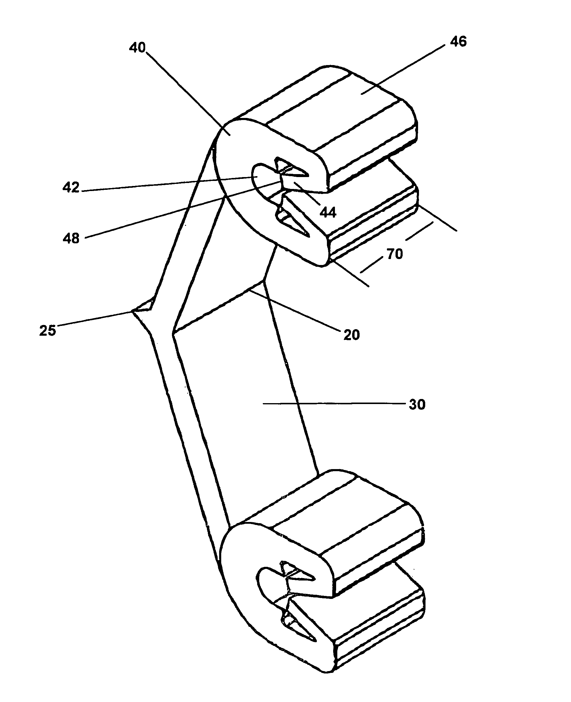
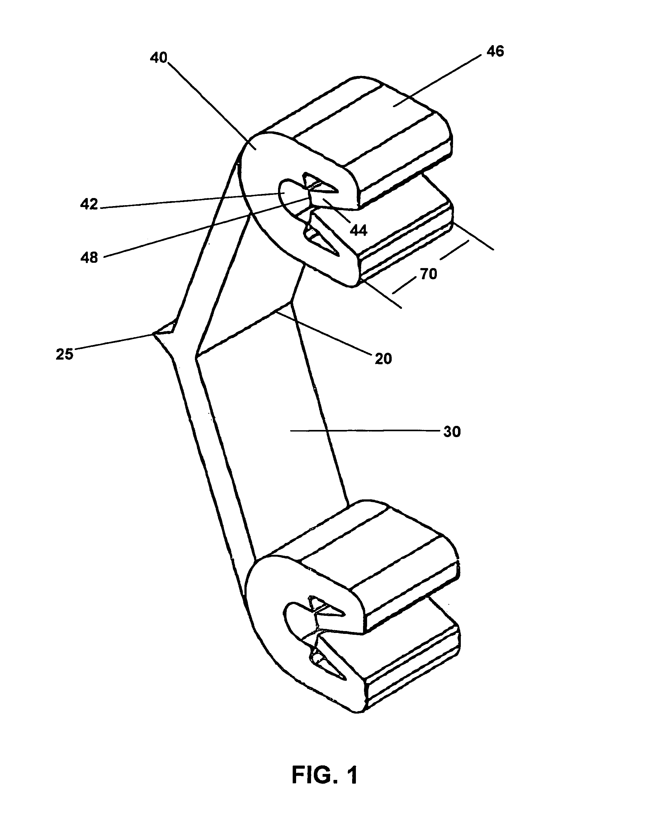
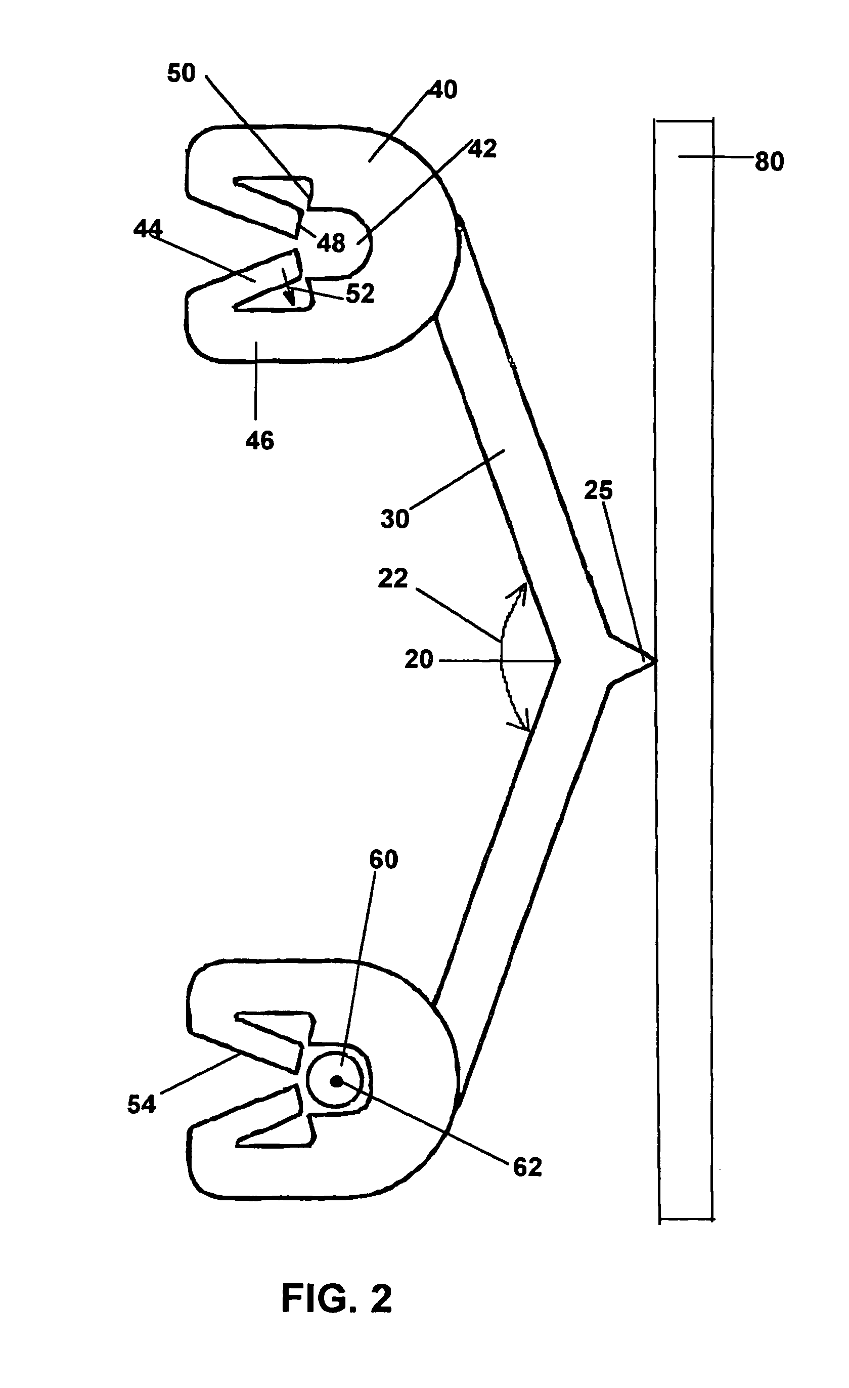
[0020]The V shaped cage spacer 10 has a pair of legs 30, which meet at a junction 20 and support spaced apart clip portions 40. The junction 20 preferably has a pointed apex 25 having a small footprint for engaging a mold wall.
[0021]The angle 22 at the junction 20 and length of the legs 30 determine the distance of the tip of the apex 25 from the rebar or welded fabric 60, thus spacing a mold wall a specified distance from the plane formed by the rebar or welded fabric 60. The length of the legs 30 and the angle 22 also determine how far apart the clips 40 are from each other so that they can be lined up with and attach to rerods or welded fabric.
[0022]The angles 22 and leg lengths 30 can be varied for any desired spacing between a mold wall and the rebars or welded fabric. It is important to have the spacers hold the rebars or welded fabric a specified distance from the mold wall to ensure proper reinforcing strength in concrete provided by the rebars or welded fabric.
[0023]Clip 40...
PUM
 Abstract
Description
Claims
Application Information
 - R&D
- Intellectual Property
- Life Sciences
- Materials
- Tech Scout
- Unparalleled Data Quality
- Higher Quality Content
- 60% Fewer Hallucinations
Browse by: Latest US Patents, China's latest patents, Technical Efficacy Thesaurus, Application Domain, Technology Topic, Popular Technical Reports.
© 2025 PatSnap. All rights reserved.Legal|Privacy policy|Modern Slavery Act Transparency Statement|Sitemap|About US| Contact US: help@patsnap.com


