Auditorium seating

a seating and auditorium technology, applied in the field of seating devices, can solve the problems of prone to damage and/or premature wear, difficult installation, and inability to adjust the angular position of the pivot arm relative to the structural member defining the stowed position

Inactive Publication Date: 2005-05-31
RAM MACHINE 1990 +1
View PDF64 Cites 33 Cited by
  • Summary
  • Abstract
  • Description
  • Claims
  • Application Information

AI Technical Summary

Benefits of technology

[0011]The seating apparatus can further include anti-rotate means adjacent the bushing and the bore for preventing relative motion between the bushing and bore. The anti-rotate means can include an axial groove along the outer surface of the bushing and a radially inwardly directed key extending from the inner surface of the bore and engaging the groove of the bushing.

Problems solved by technology

The tension springs can be difficult to install, and generally remain exposed so that they are prone to damage and / or premature wear.
Furthermore, in known seating systems having seats attached to pivot arms, the angular position of the pivot arm relative to the structural member defining the stowed position is not adjustable once the seating system has been manufactured and assembled.
Accordingly, due to variations in the manufacturing and assembly of the seating systems, adjacent seats in a row of seating may not have uniform stowed positions.
An excessive gap between the seat and the desk when in the stowed position can obstruct aisles between adjacent rows of seats.
Having no space at all between the seat and the desk when in the stowed position can cause wear or damage to the seat and the desk.
As well, seats having different spacings between the seats and the desk when in the stowed position can create an untidy appearance.
Accordingly, the uprights can be rather costly.
These joints are rather complex and can be costly to produce.

Method used


Image

  • Auditorium seating
  • Auditorium seating
  • Auditorium seating

Examples


Embodiment Construction

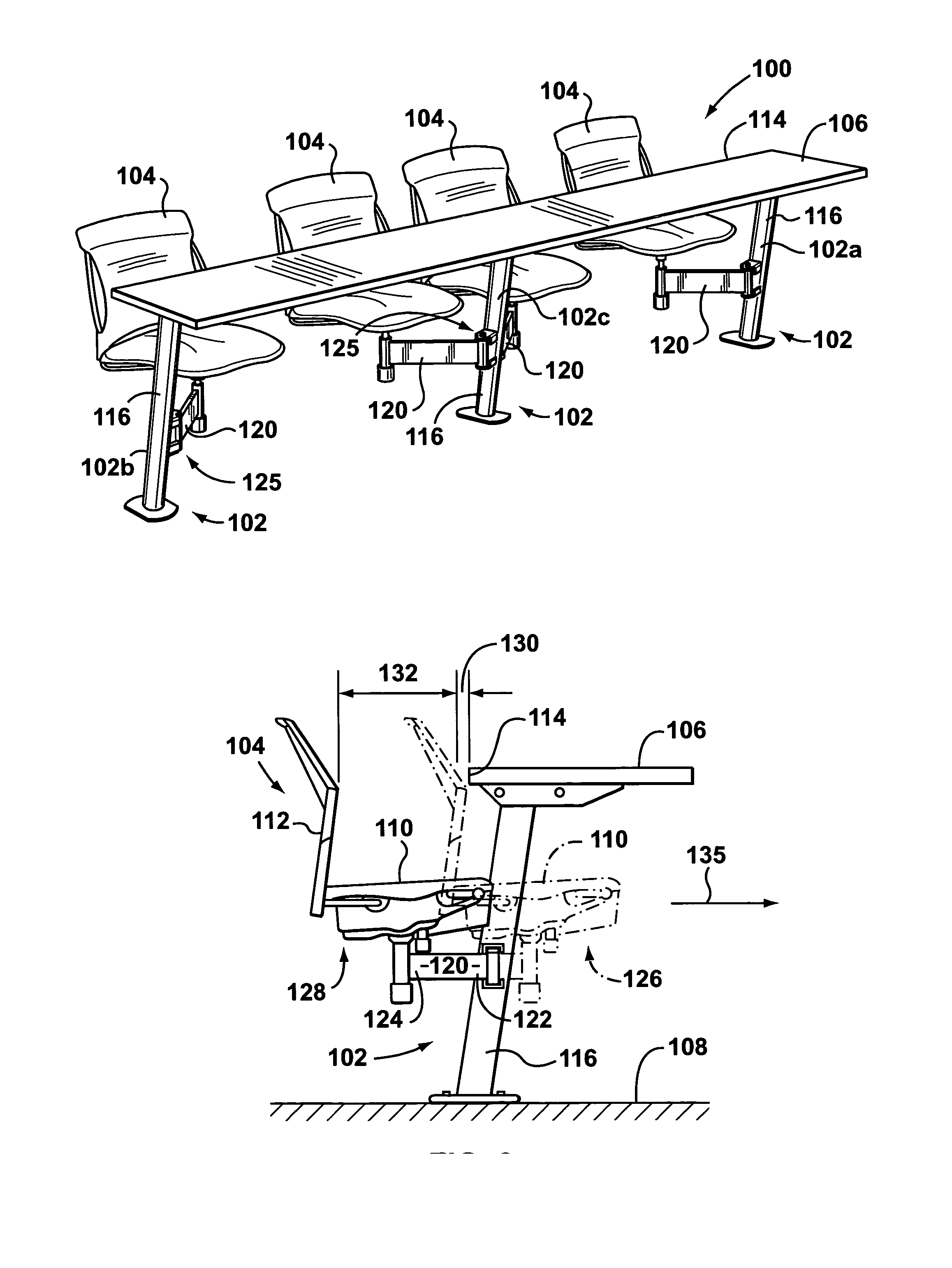
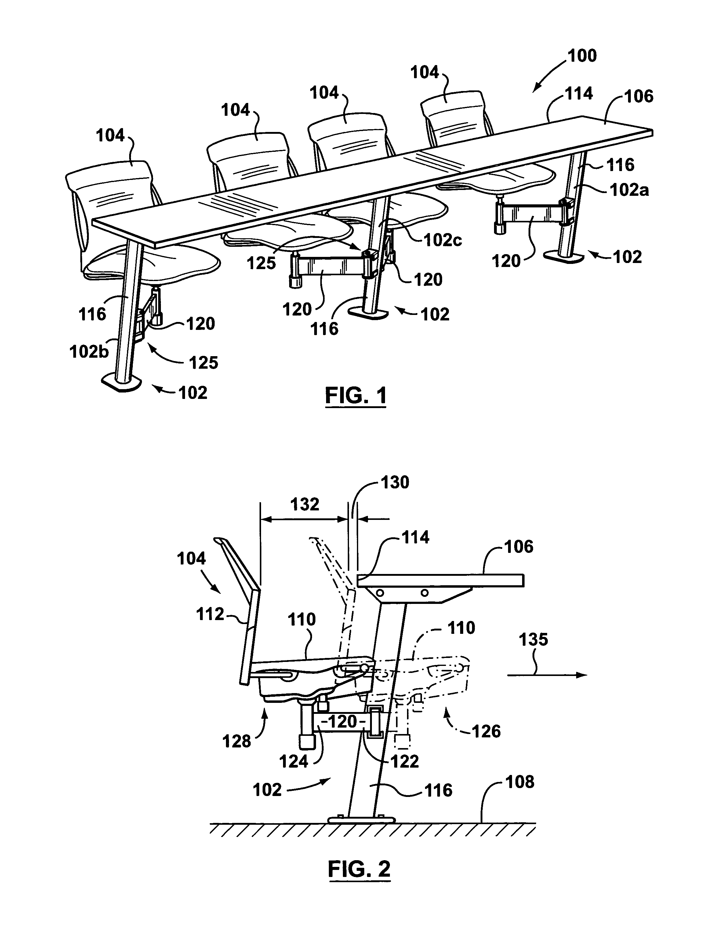
[0033]A seating apparatus according to the present invention is shown generally at 100 in the Figures. Referring to FIGS. 1 and 2, the apparatus 100 has at least one support element 102 for supporting a seat 104 and a work surface 106 above a floor 108.

[0034]The seats 104 can have a seat base 110 and a backrest 112. The work surface 106 can be a panel constructed of high pressure laminate. The work surface 106 presents an adjacent edge 114 that faces the backrests 112 of the seats 104.

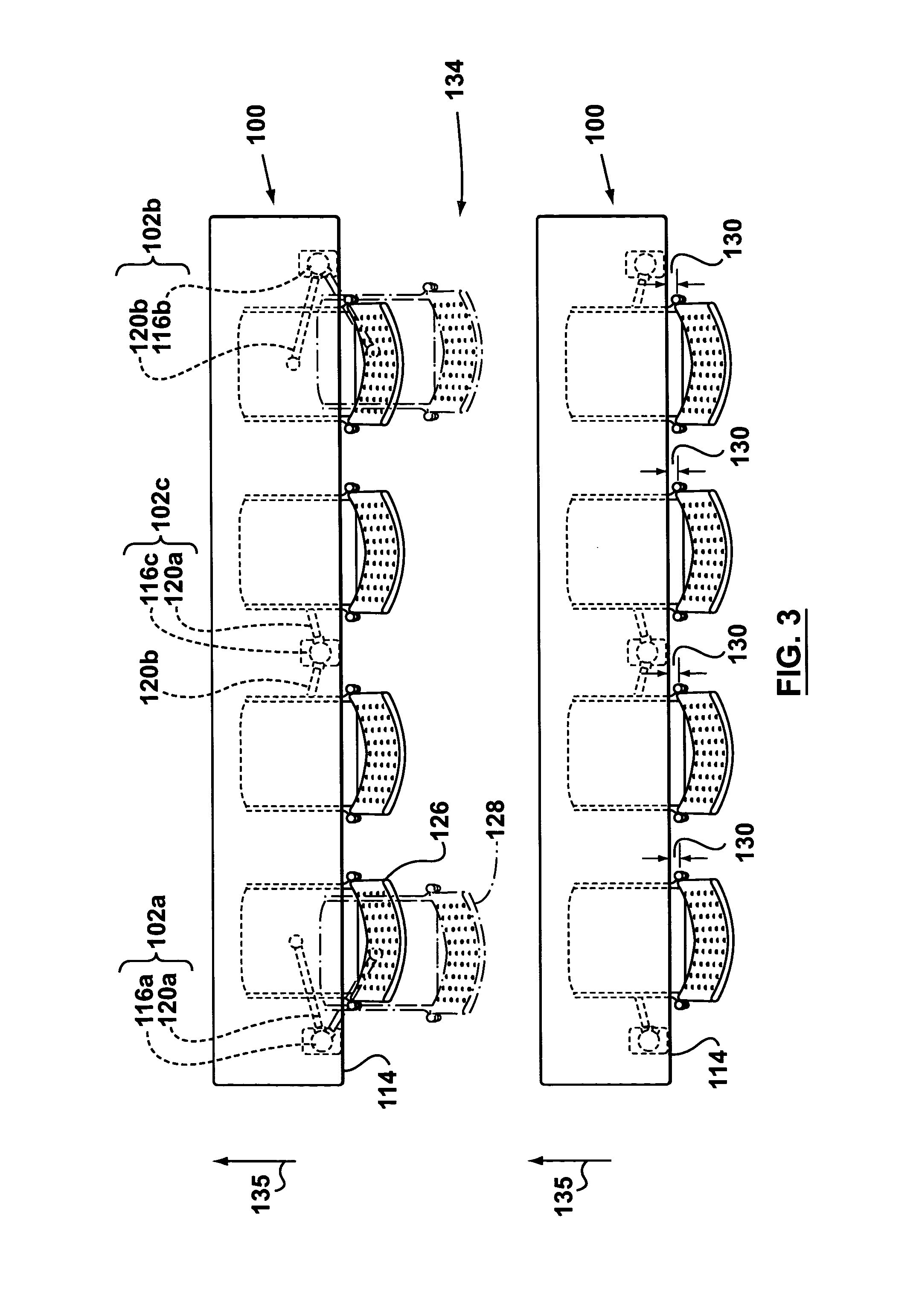
[0035]Each support element 102 comprises an upright 116 and at least one swing arm 120 pivotably mounted to the upright 116. Each swing arm 120 has an inner end 122 and an outer end 124. The inner end 122 of the swing arm 120 is pivotably attached to the upright 116 by means of a pivot joint 125. The outer ends 124 of the swing arms 120 support the seats 104.

[0036]The swing arms 120 are pivotable between stowed positions, identified at 126 (in phantom line) in FIG. 2, and deployed positions, identified...


PUM


Abstract

A seating apparatus has a support element having an upright extending from a floor and a swing arm pivotably mounted to the upright about a generally vertical pivot axis. A work surface is secured to the upright above the swing arm, and a seat is mounted on the swing arm, the seat having a seat base upon which an occupant can be seated. The swing arm is pivotable between a stowed position wherein the seat base is tucked substantially underneath the work surface, and a deployed position wherein the seat base is substantially clear of the work surface. The seating apparatus is also provided with a flat coiled torsion spring for biasing the arm to the stowed position, the torsion spring having a first end fixed directly or indirectly to the upright and a second end fixed directly or indirectly to the swing arm.

Description

FIELD OF THE INVENTION[0001]This invention relates to a seating apparatus for use in auditoriums, lecture halls, cafeterias, meeting rooms, and the like.BACKGROUND OF THE INVENTION[0002]Seating systems that provide seating with attached desks or work surfaces are often convenient for use in lecture halls, classrooms, meeting rooms, or similar facilities. Some existing seating systems of this type have desks or work surfaces supported above a floor by structural support elements. Seats are attached to the support elements by a pivot arm extending from the support element, so that the seat can be stowed under the desk when not in use.[0003]It is known to include biasing means in these seating systems to bias the swing arm to the stowed position. The biasing means in known seating systems comprises a tension spring having one end fixed to the structural member, and the other end fixed at a point along the length of the arm. The tension springs can be difficult to install, and generally...

Claims


Application Information

Patent Timeline
Patent Type & Authority Patents(United States)
IPC IPC(8): A47C1/00A47C1/12A47C7/00A47B83/02
CPCA47B83/02A47C9/022A47C7/002A47C1/12
Inventor PERNICKA, VACLAVSHATS, MICHAEL
Owner RAM MACHINE 1990
Why Eureka
Try Eureka