Cam-driven four-way head restraint assembly

a head restraint and cam technology, applied in the field of head restraint assembly, can solve the problems of inconvenient use, inconvenient assembly, and complex components of the device, and achieve the effects of improving the aesthetic appearance, improving the position retention of the head restraint, and improving the positive stop

Inactive Publication Date: 2005-05-31
LEAR CORP
View PDF29 Cites 112 Cited by
  • Summary
  • Abstract
  • Description
  • Claims
  • Application Information

AI Technical Summary

Benefits of technology

[0015]Accordingly, one advantage of the present invention is that it provides fore / aft movement of the head restraint including positive stops for improved head restraint position retention.
[0016]Another advantage of the present invention is that it provides dual positive stop mechanisms to improve positive stops at predetermined fore / aft adjustment positions.
[0017]Yet another advantage of the present invention is that it provides a single control for both vertical and fore / aft movement of the head restraint assembly which improves the aesthetic appearance as well as ergonomic operation of the head restraint movement.
[0018]Still another advantage of the present invention is that it provides dual positive stop mechanisms to improve releasable locking at predetermined vertical adjustment positions.
[0019]Still another advantage of the present invention is that it provides universal parts for an opposable build operation which reduces manufacturing and assembly time and cost.

Problems solved by technology

However, the Andres et al. device requires complex components, such as a bellows and a motor to accomplish the fore / aft movement.
However, the Vidwans et al. device does not provide a positive stop that secures and maintains the headrest in the desired fore or aft position during sudden movement or rear impact of a vehicle.
However, this is opposite to the direction necessary for providing restraint to the head of a seat occupant upon rear impact or other sudden forward vehicle movement.
Additionally, the Chung device requires that a seat occupant undergo a series of steps to adjust the headrest assembly from an aft position to a fore position which is ergonomically undesirable.
While the Holstensson device may provide a positive stop of the headrest assembly in fore / aft positions, the fore / aft adjustment is limited to small incremental movements governed by the rate at which the seat occupant rotates the knob.
This limitation may be ergonomically undesirable when adjusting from an aft-most position to a foremost position or vice versa.
This results in a device that is overly complex and ultimately less cost effective to assemble.
While the head restraint assemblies providing four-way adjustment of the type known in the related art have generally worked for their intended purposes, they suffer from the disadvantage that they generally fail to provide a positive stop or provide only a single positive stop or a positive stop in the opposite direction with respect to movement of the head and neck in the event of a sudden rear impact or forward acceleration.
In addition, the head restraint assemblies providing four-way adjustment of the type known in the related art also suffer from undesirable ergonomic features and / or complex assemblies including motors and control components.

Method used


Image

  • Cam-driven four-way head restraint assembly
  • Cam-driven four-way head restraint assembly
  • Cam-driven four-way head restraint assembly

Examples


Embodiment Construction

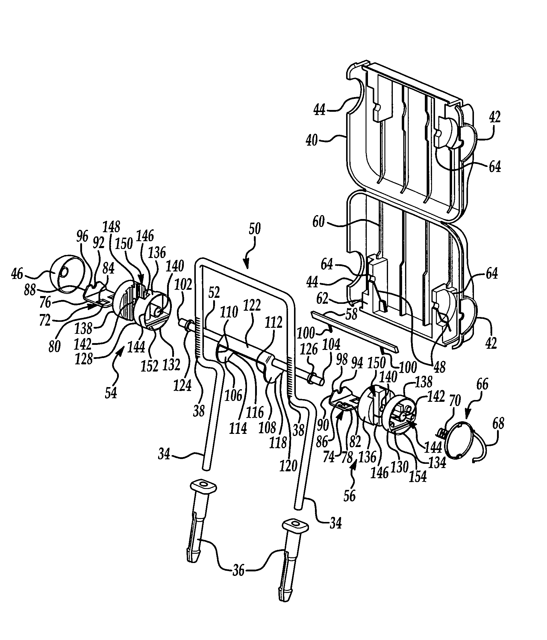
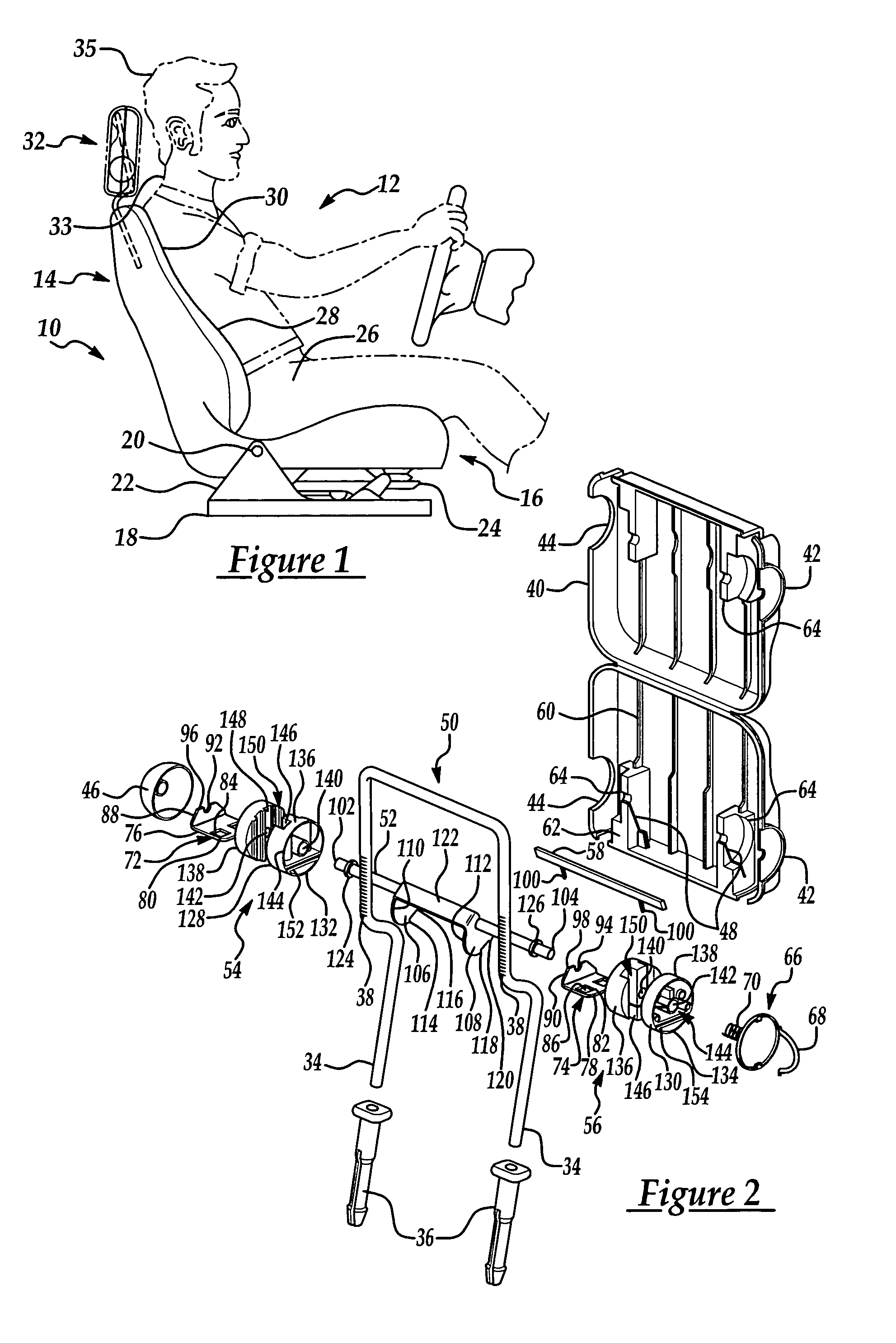
[0026]Referring now to the drawings where like numerals are used to designate like structure throughout the figures, a vehicle seat of the type that may employ a head restraint assembly of the present invention is generally indicated at 10 in FIG. 1. A theoretical “occupant” is schematically indicated at 12 and is shown in what could be referred to as a “normal driving position.” The vehicle seat 10 includes a seatback, generally indicated at 14, a lower seat assembly, generally indicated at 16 that is supported on a seat track 18, as is commonly known in the art. The seatback 14 may be pivotally connected about a pivot point 20 to the lower seat assembly 16 by means of a bracket 22 that forms a part of the seat track mechanism 18. In this way, the seat assembly 10 may be adapted to recline or adjust in a number of ways that are commonly known in the art. Furthermore, the lower seat assembly 16 may also include some sort of suspension or support mechanism 24 that adds comfort to the...


PUM


Abstract

The present invention relates to a head restraint assembly providing four-way adjustment and having dual positive stops as well as a single ergonomic control. The present invention includes a frame and a housing that engages a portion of the frame. The present invention further includes a cam assembly disposed within the housing to provide fore / aft adjustment of the housing relative to the frame. The cam assembly includes a camshaft and at least two drum assemblies supported by the camshaft. The cam assembly further includes a contact plate extending parallel to the camshaft to releasably engage the drum assemblies. The camshaft is connected to the contact plate to provide releasable engagement between the contact plate and the drum assemblies. The present invention further includes a control member to engage the cam assembly and provide for fore / aft and vertical adjustment in response to user input.

Description

BACKGROUND OF THE INVENTION[0001]1. Field of the Invention[0002]The present invention relates, generally, to a head restraint assembly for a vehicle seat. More specifically, the present invention relates to a cam-driven four-way head restraint assembly for a vehicle seat that provides a single control for cam-driven, four-way adjustment and incremental dual positive stops at each adjustment location.[0003]2. Description of the Related Art[0004]Conventional vehicle seat designs of the type commonly found in the related art typically include a seatback assembly, a lower seat assembly, recliner mechanism, manual or power adjustment mechanism for adjusting a number of positions of either the seatback or lower seat assemblies, as well as a number of safety features including occupant restraint devices such as seatbelts. The seatback assembly also includes a head restraint that is typically mounted at the top or upper end of the seatback.[0005]Head restraint assemblies for vehicle seats a...

Claims


Application Information

Patent Timeline
Patent Type & Authority Patents(United States)
IPC IPC(8): A47C7/36B60N2/48
CPCB60N2/4817B60N2/4852B60N2/485B60N2002/4894B60N2/818B60N2/85B60N2/853B60N2/894
Inventor YETUKURI, NAGARJUNFARQUHAR, MARKSMALLWOOD, DALEWIER, PAULMCQUEEN, KENNETHPHAN, MICHAEL
Owner LEAR CORP
Why Eureka
Try Eureka