Dual action mechanical assisted connector

a mechanical assisted connector and double action technology, applied in the direction of coupling device connection, coupling/disassembly parts, electrical apparatus, etc., can solve the problems of increasing product costs, and affecting the work efficiency of electrical connectors. , to achieve the effect of eliminating alignment errors, and reducing the required mating for

Active Publication Date: 2005-05-31
J S T CORP
View PDF39 Cites 32 Cited by
  • Summary
  • Abstract
  • Description
  • Claims
  • Application Information

AI Technical Summary

Benefits of technology

[0011]The present invention provides a simple, powerful, and inexpensive electrical connector assembly to securely and confidently join male and female electrical connector structures to ensure electrical continuity and complete electrical circuits.
[0014]The present lever-type electrical connector assembly invention reduces required connecting mating forces by employing a connector structure that includes two cam follower projections. The housing assembly includes a base housing for receiving the connector structure. The base housing includes two cam grooves and a sliding guide rail. Also, a slide lever housing is mounted on the base housing. The slide lever housing includes a sliding projection engaged in a sliding guide rail. The slide lever housing also has a second sliding guide rail that receives a second sliding projection that is part of a cover housing. The cover housing is pivotally mounted on the base housing.
[0015]The present invention eliminates alignment errors while simultaneously reducing the required mating forces by means of a lever assembly and camming system that provides a dual action mechanical assist to establish an intimate electrical connection between male and female connector structures. The present invention employs a novel cam groove geometry that results in mating forces that are substantially constant throughout the mating operation.
[0016]The method of the present invention allows users to securely and reliably mate connectors with large numbers of pins and high mating forces, while at the same time preventing alignment errors, eliminating intermittent connections, and improving reliability of the overall product.

Problems solved by technology

The task of securely and reliably joining multi-pin electrical connectors presents a difficult challenge as the number of pins increases and the corresponding required mating forces likewise increase.
With large forces necessary, an alignment error of the male and female structures may result in inordinately high stress on the individual pins resulting in cracked conductors or damaged insulators, as well as pushed pins that fail to meet and join a corresponding receptacle.
These maladies then result in faulty or intermittent connections and greatly increase product costs as extensive troubleshooting may be required to detect the faulty assembly once the product is assembled.

Method used


Image

  • Dual action mechanical assisted connector
  • Dual action mechanical assisted connector
  • Dual action mechanical assisted connector

Examples


Embodiment Construction

[0029]The invention is described in detail with particular reference to certain preferred embodiments, but within the spirit and scope of the invention, it is not limited to such embodiments. It will be apparent to those of skill in the art that various features, variations, and modifications can be included or excluded, within the limits defined by the claims and the requirements of a particular use.

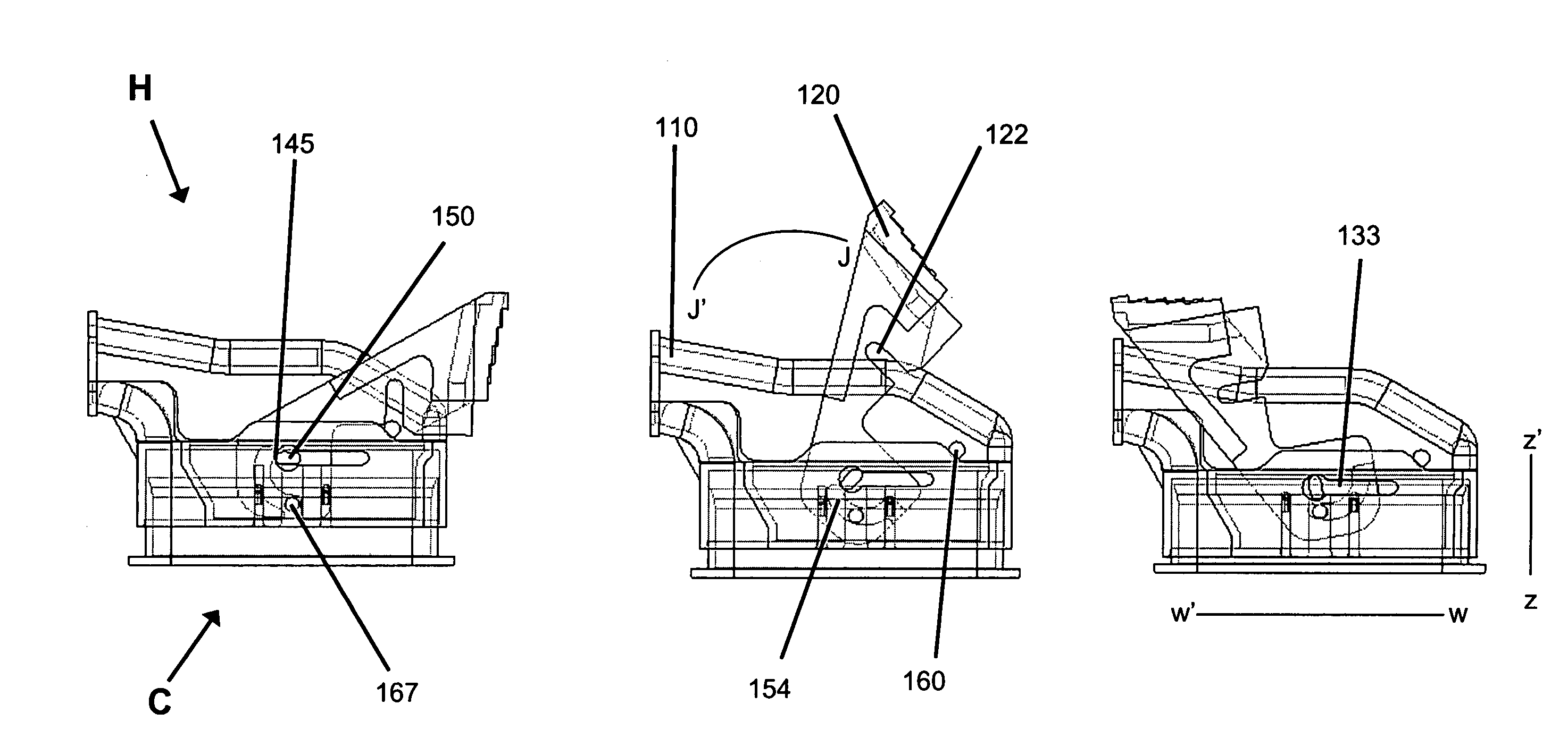
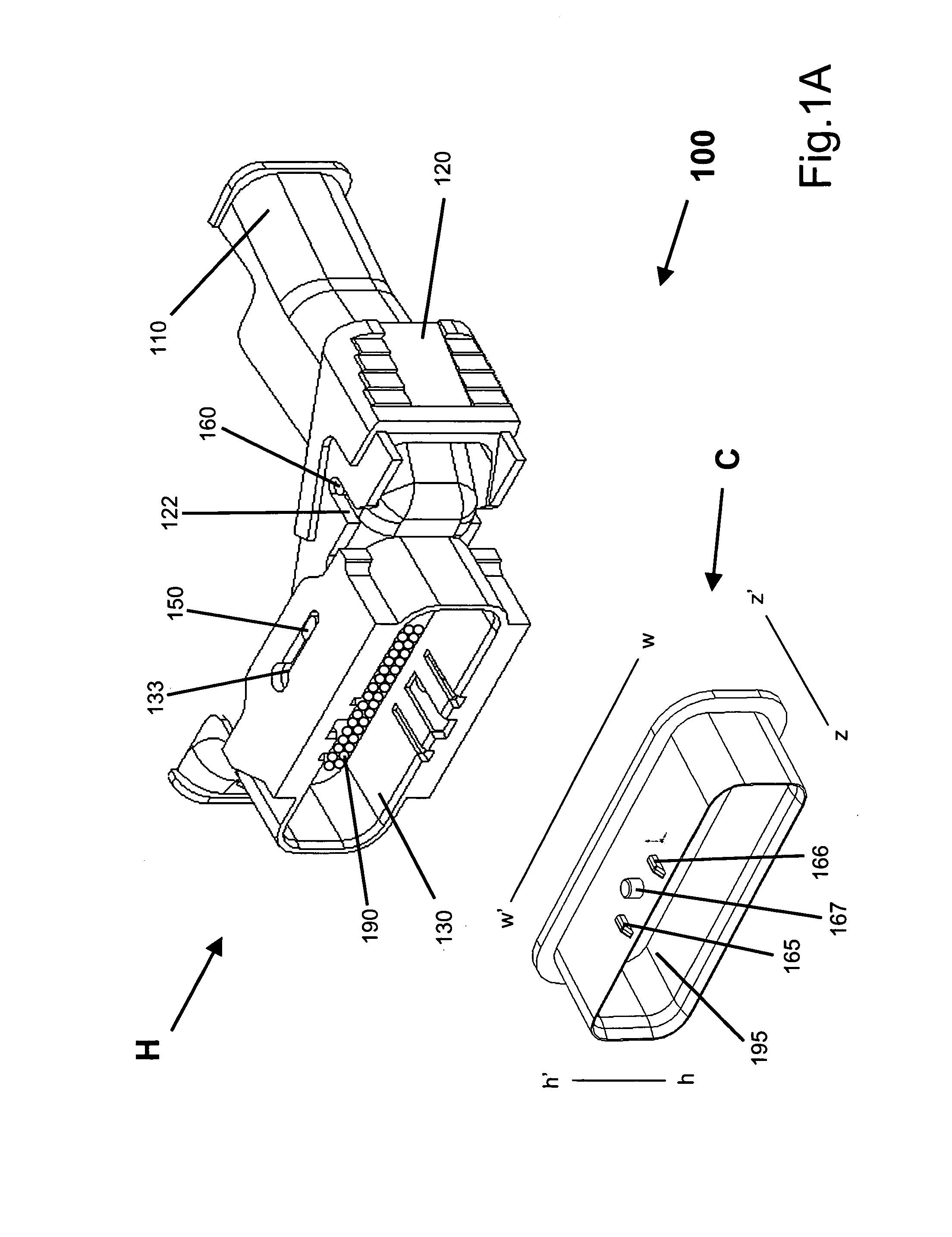
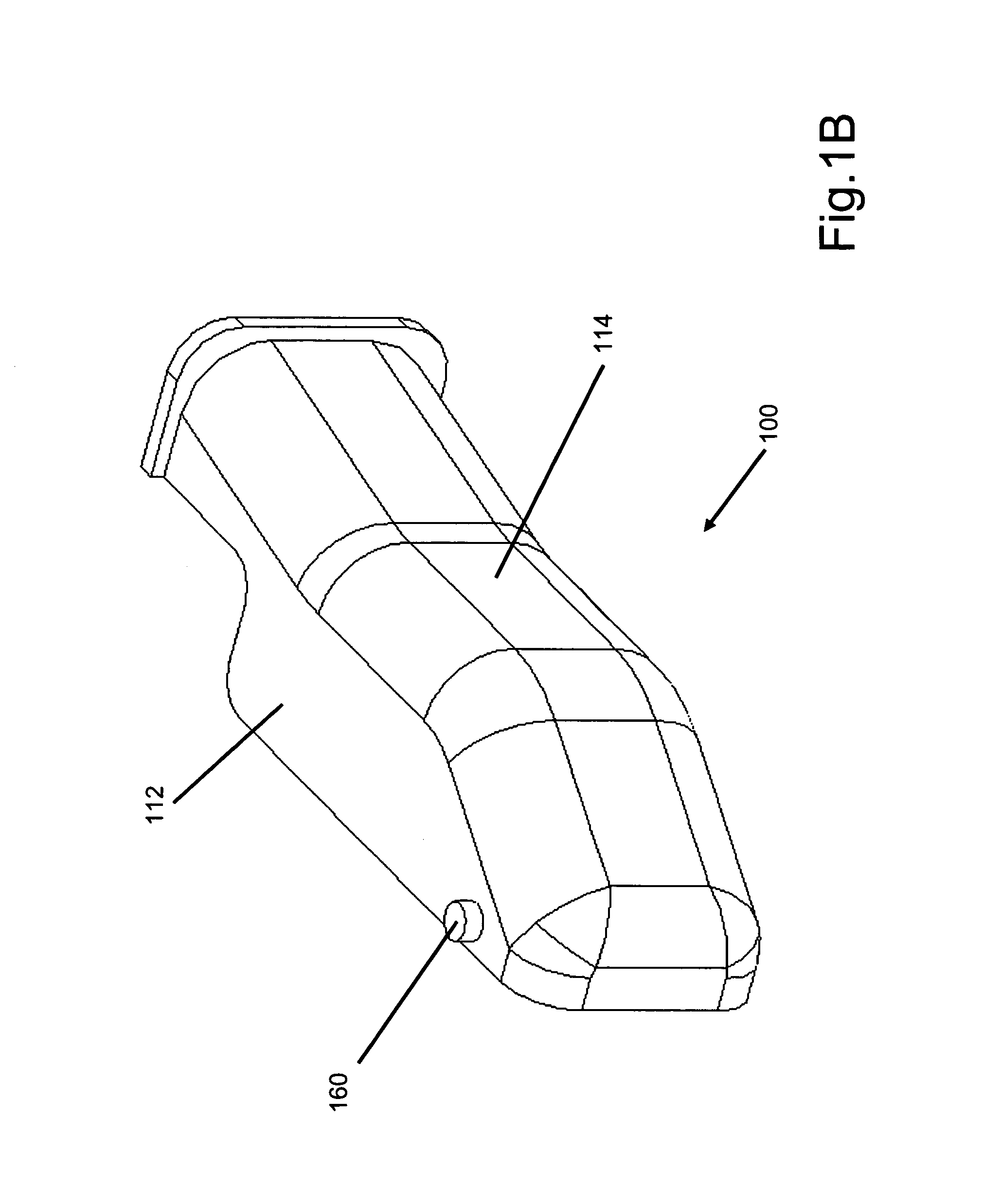
[0030]The present invention extends the functionality of current electrical connector assemblies by properly and consistently aligning multi-pin connectors and joining the structures with reduced mating forces. Once joined, the electrical connector assembly of the present invention is secured using the lever housing to ensure that the connection does not loosen or otherwise disconnect over time. This has many advantages over prior assemblies such as those providing simple cam slides, because the dual action mechanical assistance provided by the present invention significantly reduces th...


PUM


Abstract

A lever-type electrical connector assembly reduces the connection mating forces required to mate female and male connectors. The connector assembly employs a first connector with cam follower projections, a base housing with cam grooves and a sliding guide rail, a slide lever housing including a sliding projection and a sliding guide rail, and a cover housing pivotally mounted on the base housing, the cover housing having a sliding projection. As the cover housing is rotated from an open to a closed position, it engages the sliding projection in the guide rail to permit rotation of the lever housing. This rotation engages the sliding projection in the guide rail. As the lever housing is rotated from an open to a closed position, it rotates the cam grooves to engage the cam follower projections thereby drawing the first connector into the base housing to a connected position.

Description

FIELD OF THE INVENTION[0001]The invention relates generally to electrical connector assemblies. More particularly, the invention relates to an electrical connector assembly with a lever mechanism to securely mate and un-mate the connectors with a reduced mating force as a cover housing and a lever housing are rotated.BACKGROUND OF THE INVENTION[0002]Electrical connector assemblies used in automotive and other applications often employ a large number of terminals and therefore require a large mating force to ensure a secure connection between the male and female connectors. Significant frictional forces from the terminals and housings must be overcome to properly join the connectors. However, assembly specifications for these connector assemblies include maximum mating force limits to prevent damage to the connectors or terminals during mating and to insure that an operator can easily and reliably mate the two connectors. These opposing constraints must both be satisfied for a connec...

Claims


Application Information

Patent Timeline
Patent Type & Authority Patents(United States)
IPC IPC(8): H01R13/629
CPCH01R13/62938H01R13/62955H01R13/629
Inventor OSADA, TSUYOSHI
Owner J S T CORP
Why Eureka
Try Eureka