Eureka AIR delivers breakthrough ideas for toughest innovation challenges, trusted by R&D personnel around the world.

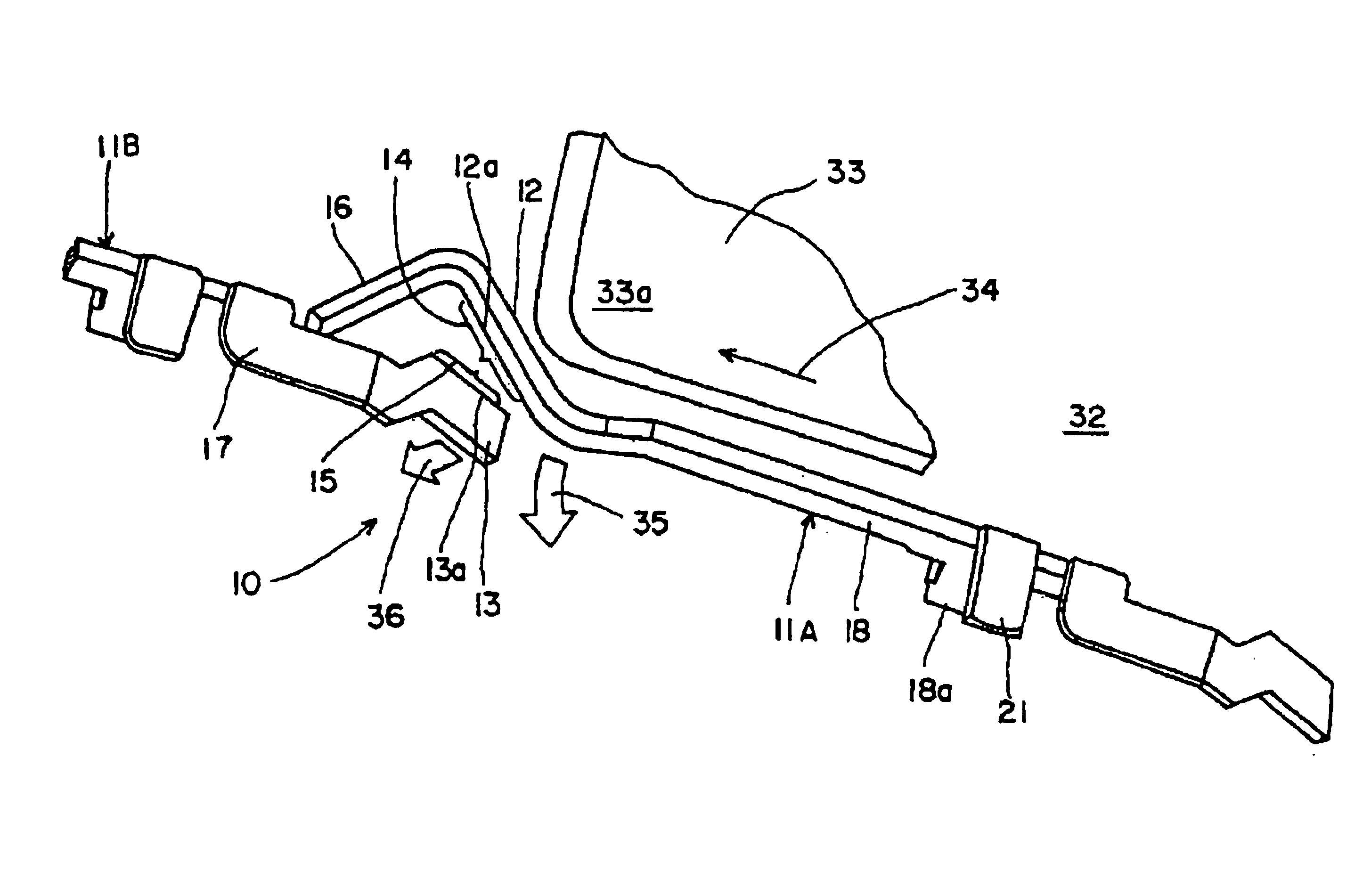
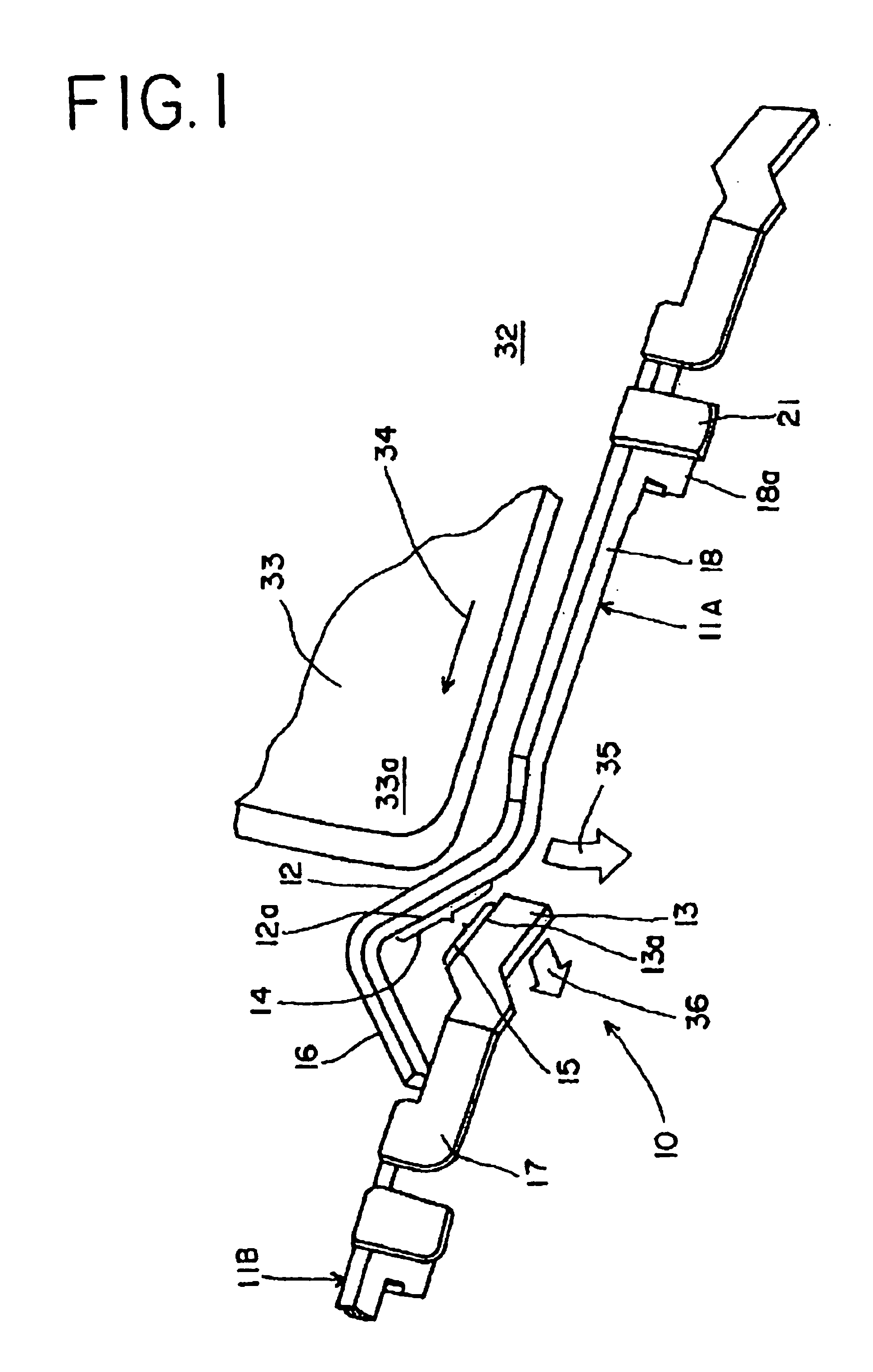
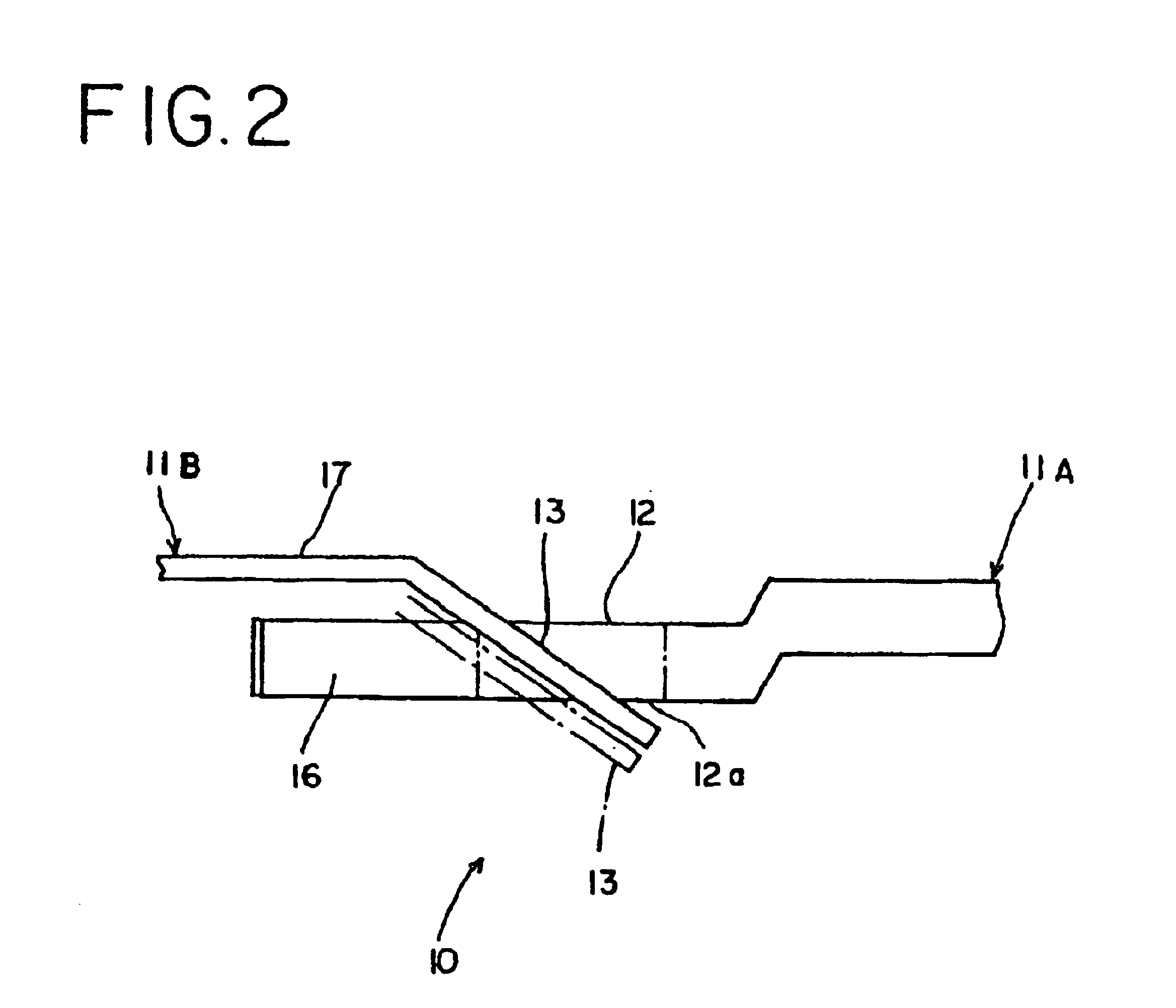
Detection switch mounted in a card socket

a technology of detection switch and card socket, which is applied in the direction of electrical apparatus casing/cabinet/drawer, coupling device connection, instruments, etc., can solve the problems of inability to effectively reduce the cost of sockets equipped with switches, unfavorable effective reduction of costs, and relatively high manufacturing, assembly and inventory costs. achieve the effect of stable switching action

Inactive Publication Date: 2005-05-31
MOLEX INC
View PDF4 Cites 22 Cited by
  • Summary
  • Abstract
  • Description
  • Claims
  • Application Information

AI Technical Summary

Benefits of technology

[0007]Therefore, one object of the present invention is to provide a detection switch for a card socket which assures that the switching action is stable and includes contacts which utilize a wiping action to ensure such stability.

Problems solved by technology

The contact members of a detection switch are likely to collect particles of foreign substance or to have oxide coating formed thereon, thus contributing to unstable switching conditions—particularly in a detection switch that does not include wiping action such as that shown in the conventional switch of FIG.
This contributes to the overall relatively high manufacturing, assembly and inventory costs and does not allow for the effective reduction of costs for sockets equipped with switches.
This type of design is not necessarily cost effective or simple.

Method used


Image

  • Detection switch mounted in a card socket
  • Detection switch mounted in a card socket
  • Detection switch mounted in a card socket

Examples


third embodiment

[0050]the detection switch is shown in FIGS. 11 through 13. A card socket 90 has three contact members 71A, 71B and 71C arranged in series on one longitudinal side of “U”-shaped housing 91. A first detection switch 70 is made by the contact members 71A and 71B, and a second detection switch 70 is made by contact members 71B and 71C.

first embodiment

[0051]As in the first embodiment, each contact member is made by stamping and forming a thin metal sheet into the configuration shown in FIGS. 12 and 13. Specifically, each contact comprises a shank 78 having a front or head contact and a rear or tail contact integrally connected thereto. The head contact comprises up and down slopes 72 and 76 that form a “V” shaped contact in the card-width parallel plane, and a first planar contact 74 integrally connected to the end of down slope 76. The tail contact comprises a second planar contact 75 integrally connected to the end of shank 78, and includes a contact projection 75a formed on one side thereof (see FIG. 13).

[0052]The shanks 78 of contact members 71A, 71B and 71C are mounted in longitudinal housing slot 98 of housing 91 with their “V” shaped head contacts projecting into card-receiving space 92. During its undeflected state, first planar contact 74 of contact member 71A abuts second contact 75 of contact member 71B and first conta...


PUM


Abstract

A detection switch mounted in a card socket including contact members responsive to insertion of a card into the card socket. The switch includes two or more contact members of the same design, each contact member having a switch contact formed on opposite ends. The switch contact at one end has a front contact section formed in the card width-parallel plane defining a first switch contact. The switch contact at the other end has a rear contact section formed in the card thickness-parallel direction and defines a second switch contact in confronting relation with the first contact. Insertion of the card in the card socket causes the first switch contact to move in the card width-parallel plane toward the second switch contact in the card thickness-parallel direction so that the second contact is contacted and wiped by the first contact.

Description

FIELD OF THE INVENTION[0001]The present invention relates to a card socket for receiving a card-like medium such as a memory card or SD card, and more particularly to a detection switch mounted in a card socket for detecting the presence of a card and / or preventing write-access to the card.BACKGROUND OF THE INVENTION[0002]A conventional card socket includes a card-receiving space for receiving a card such as a memory or SD card, and a detection switch to detect the presence or insertion of the card. Such a detection switch comprises contact members responsive to insertion of the card into the card-receiving space.[0003]FIG. 14 shows a conventional card socket for such cards. As shown, a card 101 is inserted in a card-receiving space 102 of a socket housing 100, which has first, second and third contact pieces 103, 104 and 105 mounted at one longitudinal side of the housing. First and third contact pieces 103 and 105 are adapted to be deflected during insertion of card 101. Second an...

Claims


Application Information

Patent Timeline
Patent Type & Authority Patents(United States)
IPC IPC(8): G06K13/08G06K13/02H05K5/02
CPCG06K7/0069H05K5/0286G06K13/08
Inventor HIRATA, TOSHIHISA
Owner MOLEX INC
Why Eureka
Eureka Blog
Learn More