
One-way clutch mechanisms and injector devices

a one-way clutch and injector device technology, which is applied in the direction of intravenous devices, injection syringes, automatic syringes, etc., can solve the problems of tight tolerances and severe limitations in the number of times the clutch could be released on a full rotation of the driving member

Inactive Publication Date: 2005-05-31
SAMS
View PDF2 Cites 412 Cited by
  • Summary
  • Abstract
  • Description
  • Claims
  • Application Information

AI Technical Summary

Benefits of technology

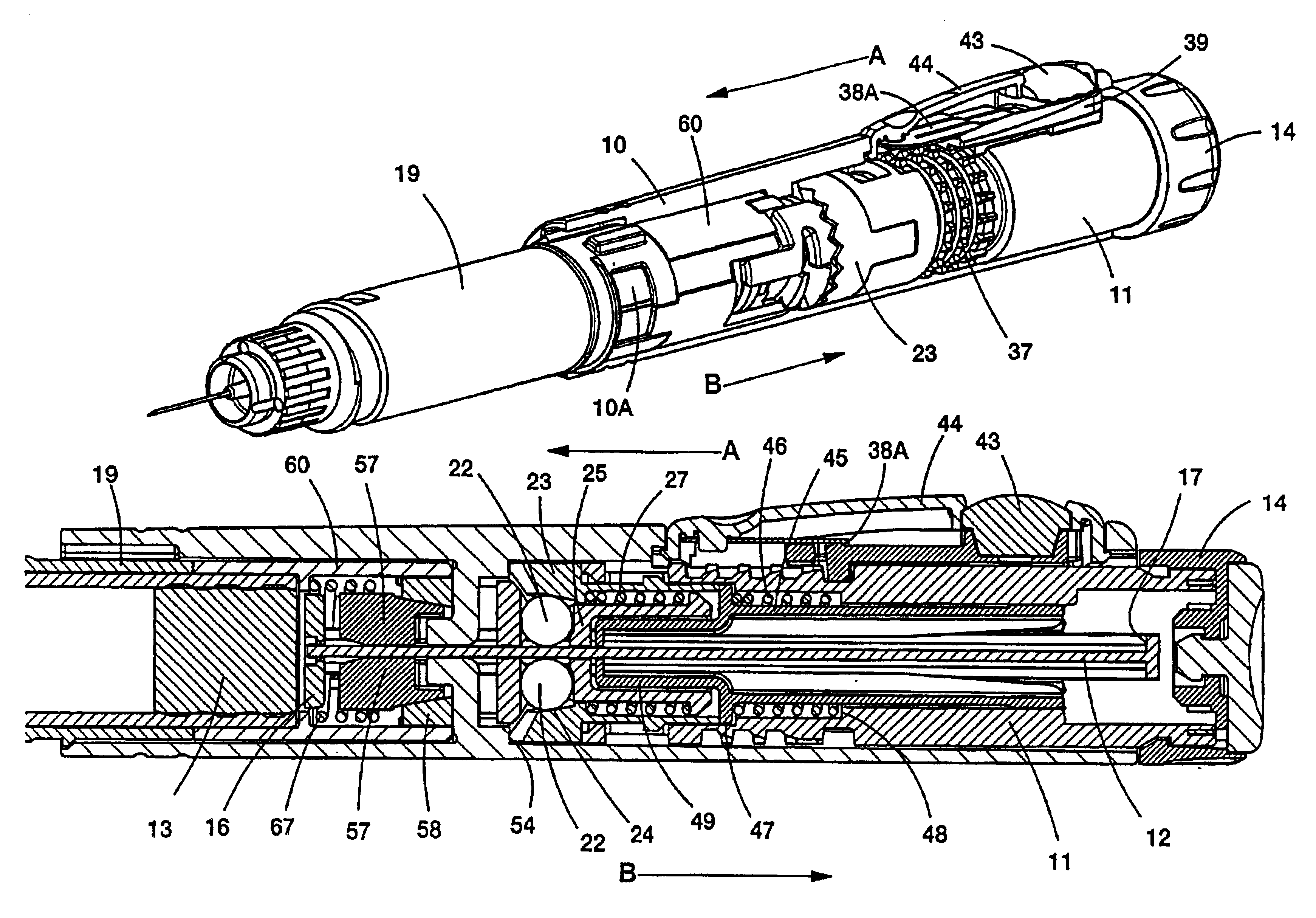
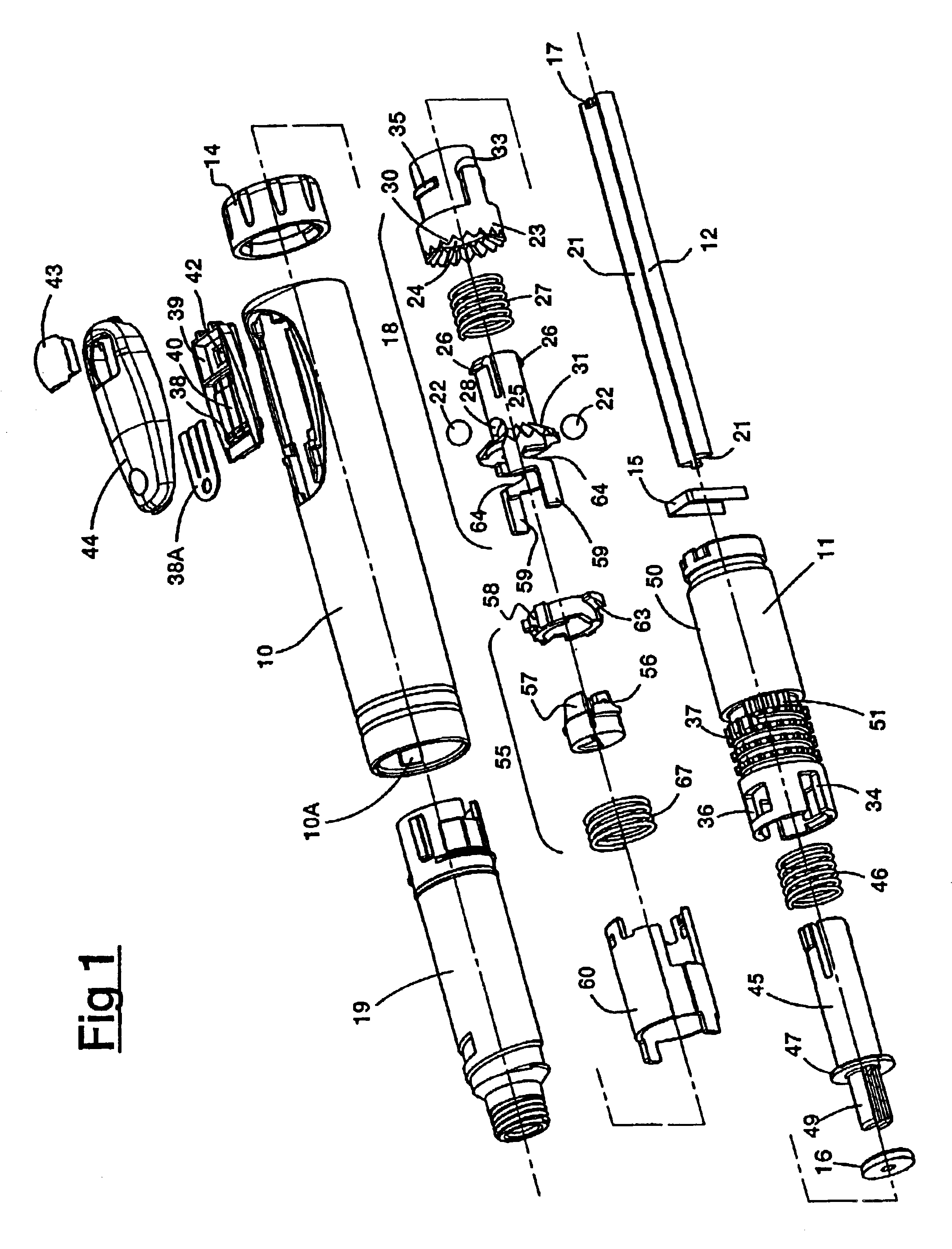
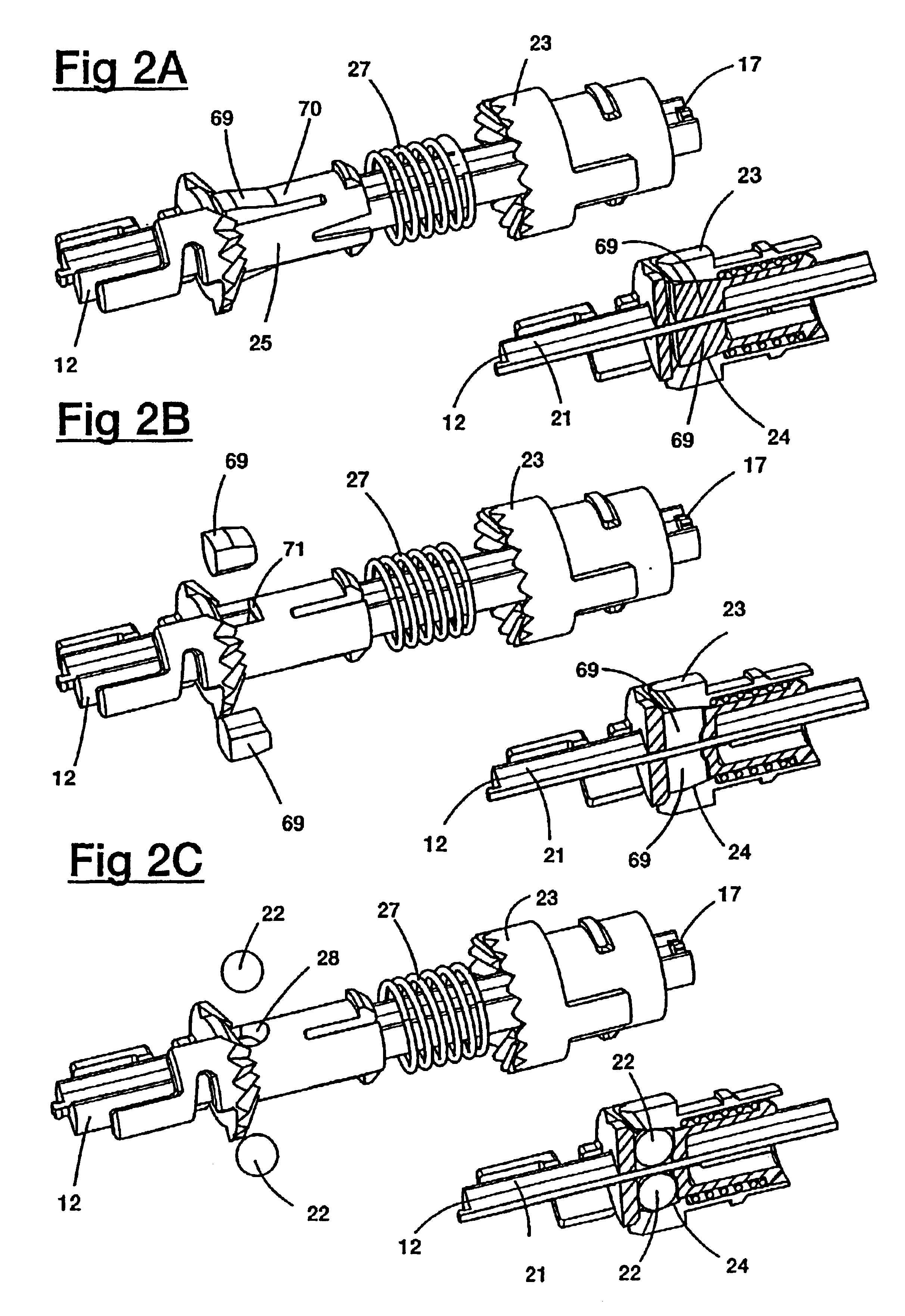
[0014]Preferably, the mechanism includes means to prevent the selection of a dose for injection which is greater than the remaining dose in a cartridge of medicament coupled to the injector. Such means may include a coupler connected to the driving member and disposed about the elongate element, the coupler having projections which are engageable with an abutment at the end of the element. During the movement of the driving member away from its starting position by the rotation thereof, the coupler will move with that driving member but when the projection on the coupler engages the abutment on the end of the element, the coupler then prevents further axial movement of the driving member. In this way, once the maximum remaining dose in a cartridge has been selected, no greater dose may be set on the driving member, for dispensing.

Problems solved by technology

This arrangement has the disadvantage that very tight tolerances are required during manufacture and also the number of times the clutch could be released on a full rotation of the driving member is severely limited.

Method used


Image

  • One-way clutch mechanisms and injector devices
  • One-way clutch mechanisms and injector devices
  • One-way clutch mechanisms and injector devices

Examples


first embodiment

[0056]The injector of FIGS. 8 and 9 differs from that of FIGS. 1 to 7 in that the one-way clutch mechanism 18 is simplified and uses only one ball, rather than the two balls of FIGS. 1 and 2C. The further one-way clutch mechanism 55 is omitted and is replaced by a simple locking washer 73 (see particularly FIG. 9A) to prevent rearward movement of the rod 12. Also, the end cap arrangement is modified in that spring 15 is omitted; rather an integral spring is formed with the modified end cap 14A. In other respects the injector corresponds to the first embodiment described above. Consequently, like parts are given like reference characters and will not be described again here.

[0057]The locking washer 73 is of pressed spring steel and has an inwardly projecting tooth 74 which locates in the channel 21 of the rod 12, forwardly of the internal wall of the tubular body 10. The washer also has two or more inwardly projecting arms 75 which are pushed into engagement with a raised boss 76 on ...

second embodiment

[0060]This modified second embodiment also includes a pre-setting facility. Some drugs may be prescribed according to body weight, age and so on, with the intention of a defined dose being given at regular times. For this purpose, the plunger 80 of this modified embodiment differs from plunger 11 and the rearward end of the injector is provided with a pre-set lock arrangement which permits the setting of a dose no greater than the pre-set amount. This pre-set lock arrangement includes a button 81 engageable with a rotatable ring 82 threadingly engaged with a pre-set stop 83, disposed around a central tubular portion 84 of the plunger 80. The end-cap 14 is also modified so as to include a central projection 85, rotatably connecting the cap to the central portion 84.

[0061]In use, pre-setting is performed by initially winding the end-cap 14 until the required dose is shown through window 42. The button 81 is then depressed which frees ring 82 for rotation; this is rotated until the pre...

third embodiment

[0063]The third embodiment, shown in FIGS. 11, 12, 13A and 13B, differs from the previous embodiments in that no plunger is provided for dispensing the dose. Instead of winding out the end-cap 14 and pressing the plunger home to deliver the medicament, the user rotates the end-cap until the desired dose appears in the window. After pushing the needle into the appropriate site, the user presses a side release button and the medicament is injected without further user participation, under the action of an internal spring. Apart from the changes required to the mechanism to give the above functionality, the mechanism is similar to the previous embodiments and insofar as is possible, like components are given like reference characters.

[0064]FIG. 12 shows the mechanism at its zero position and FIG. 11 when set to dispense a dose of medicament, immediately after release of the mechanism but before dispensing has commenced.

[0065]End-cap 90 is permanently snapped on to the rearward end of t...


PUM


Abstract

An incrementing mechanism suitable for use in a medical injector device has a driving member rotatably and slidably mounted within a tubular body and arranged to advance an elongate element in one direction with respect to the tubular body. A one-way clutch includes a generally conical surface and a blocking clutch member engageable with the conical surface. Means are provided to disengage the clutch, including a pressure component arranged and biased to engage the clutch member. Rotation of the driving member with respect to the pressure component causes two sets of inter-engageable teeth to ride over each other, which successively lifts the pressure component to disengage the clutch member from the conical surface and then allows the pressure component to be biased to a position where the clutch member engages the conical surface.

Description

CROSS-REFERENCE TO RELATED APPLICATIONS[0001]This application claims priority on International Application No. PCT / GBO1 / 01271, filed Mar. 22, 2001, which claims priority on British Application No. 00 07071.4, filed Mar. 24, 2000.BACKGROUND OF THE INVENTION[0002]1. Field of the invention[0003]This invention relates to automatic one-way clutch means for use in an incrementing mechanism having a driving member rotatably and slidably mounted within a tubular body and arranged to advance an elongate element in one direction with respect to the tubular body within which the element also is mounted. In addition, in its preferred aspects this invention further relates to such an incrementing mechanism adapted for use in conjunction with an injector device to permit the accurate dispensing of a required pre-set dose of a medicament, whenever the device is used. The invention further relates to an injector device per se.[0004]2. Related Art[0005]In my EP-0673482-A, I have described and claime...

Claims


Application Information

Patent Timeline
IPC IPC(8): A61M5/315
CPCA61M5/20A61M5/31551A61M5/31578A61M5/3158A61M5/31553A61M5/31538A61M5/31541A61M5/31543A61M2005/3125A61M5/3156A61M5/31593
Inventor SAMS
Owner SAMS
Learn More