Network termination of a telecommunications network

a technology for telecommunications networks and networks, applied in the direction of time-division multiplexing selection, electrical equipment, interconnection arrangements, etc., can solve the problems of high charges, access to a digital telecommunications network, and the inability of subscribers to operate only analog end instruments, so as to save connection charges and reduce customer restrain

Inactive Publication Date: 2005-05-31
ALCATEL LUCENT SAS
View PDF24 Cites 9 Cited by
  • Summary
  • Abstract
  • Description
  • Claims
  • Application Information

AI Technical Summary

Benefits of technology

[0008]It is an object of the invention to provide a network termination which is universally applicable and permits fair billing.
[0009]This object is attained by a network termination having at least one interface on the network side and having both analog and digital interfaces on the subscriber-line side, and also having a switch for switching the interface on the network side between analog and digital interfaces. The network termination is characterized in that it comprises a switching facility by which the interface on the network side is switchable from an analog one to a digital one. This also provides maximum freedom of access on the network side. A subscriber who needs a digital interface, for example because he wants to have two B channels at his free disposal, can release a digital interface or have it released. A subscriber who wants only an analog interface can

Problems solved by technology

This network termination NT thus offers maximum freedom of access on the subscriber-line side but has the disadvantage that on the network side, access is required to a digital telecom

Method used


Image

  • Network termination of a telecommunications network
  • Network termination of a telecommunications network
  • Network termination of a telecommunications network

Examples


Embodiment Construction

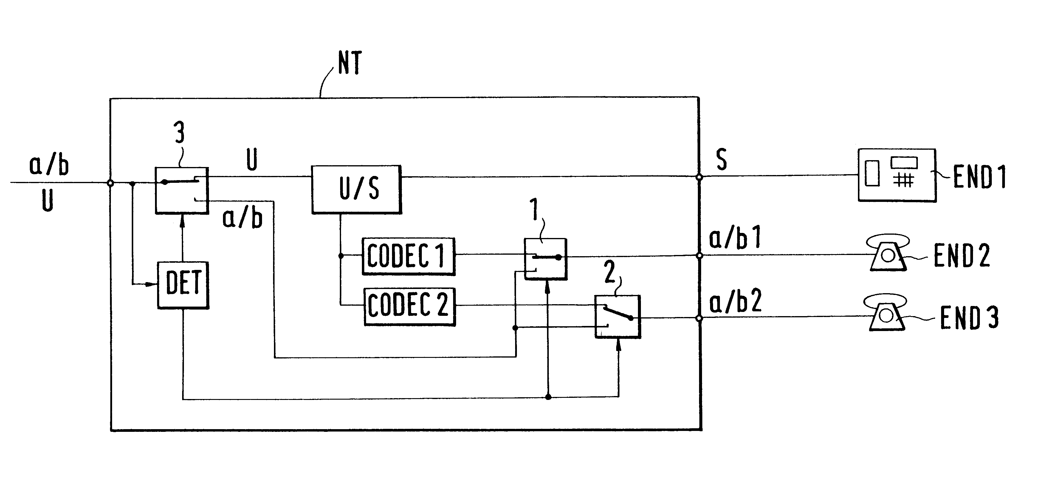
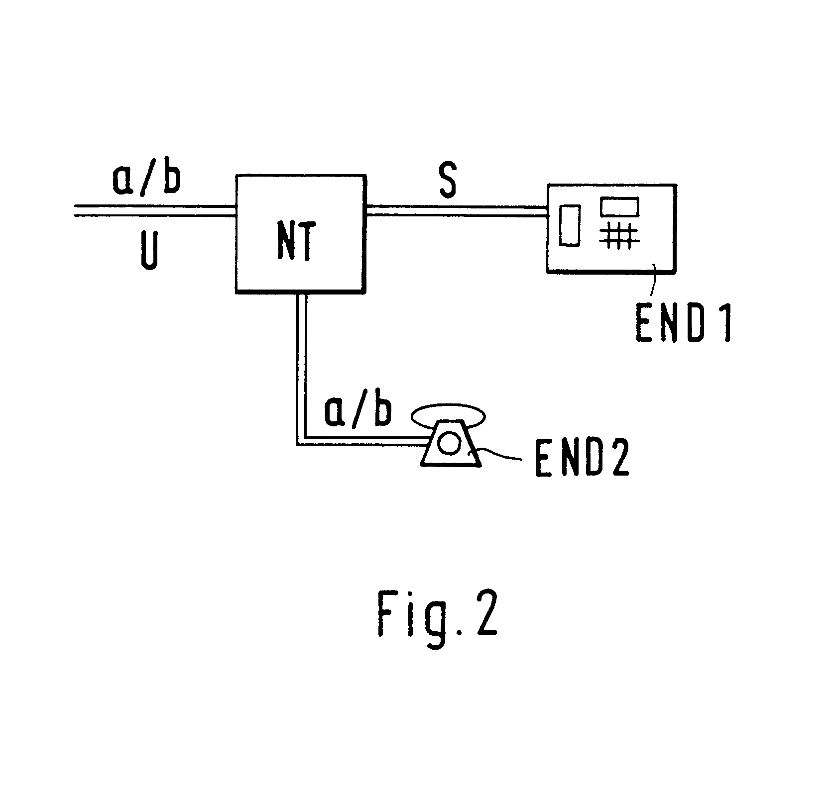
[0014]The embodiment will first be explained with the aid of FIG. 2. FIG. 2 shows a network termination NT. The network termination NT comprises an interface a / b, U on the network side to interface the network termination to a telecommunications network. Furthermore, an analog interface a / b and a digital interface S are provided on the subscriber-line side for connecting at least one analog end instrument END2 and at least one digital end instrument END1, respectively. End instrument END1 is, for example, a digital telephone or computer, and end instrument END2 is, for example, an analog telephone or a fax machine. The telecommunications network is designed to support both analog and digital transmissions, e.g., by switching, at an exchange, from an analog network to a digital network. The analog network is, for example, the plain old telephone network (POTN), and the digital network may be the integrated services digital network (ISDN).

[0015]A subscriber is to be free to choose bet...


PUM


Abstract

A network termination (NT) which is universally applicable and permits fair billing. The network termination (NT) according to the invention is characterized in that it comprises a switching facility (DET, 1, 2, 3) whereby the interface (a/b, U) on the network side is switchable from an analog one (a/b) to a digital one (U). A subscriber who needs a digital interface, for example because he wants to have two B channels of the ISDN at his free disposal, can release a digital interface (U) or have it released. A subscriber who wants only an analog access can release an analog access or have it released. To accomplish this, the network termination (NT) contains a switch (3) and a detector (DET). The switching between analog access and digital access on the network side can be effected without replacement of the network termination (NT).

Description

BACKGROUND OF THE INVENTION[0001]This invention relates to a network termination of a telecommunications network having at least one interface on the network side and both analog and digital interfaces on the subscriber-line side.[0002]A telecommunications network, particularly a telephone network, commonly comprises a number of exchanges that are connected with one another. A plurality of terminals are connected to each exchange. At the interface between each terminal and the telecommunications network, a network termination is provided.[0003]FIG. 1 illustrates how the design of a network termination has changed in the course of time. FIG. 1a shows a network termination for an all-analog telecommunications network. The network termination NT has an analog interface a / b on the network side and an analog interface a / b on the subscriber-line side. Via the analog interface on the subscriber-line side, the terminal can connect an end instrument END, such as an analog telephone, to the t...

Claims


Application Information

Patent Timeline
IPC IPC(8): H04Q11/04H04M11/00H04L29/10
CPCH04Q11/0471H04Q2213/13034H04Q2213/1309H04Q2213/1332H04Q2213/13202H04Q2213/13209H04Q2213/13299H04Q2213/13096
Inventor PETERS, WOLFGANGSCHNEIDER, GERHARD
Owner ALCATEL LUCENT SAS
Why Eureka
Try Eureka