Device having pivotable wheel mechanism

a technology of a pivoting wheel and a device, which is applied in the direction of special foundation layout, support, understructure, etc., can solve the problems of vibration and shaking of the bending brake, difficult transportation, and inability to accurately align the workpiece, so as to facilitate quick and easy assembly transportation and transportation. the effect of quick and easy transportation

Inactive Publication Date: 2005-06-07
TAPCO INTERNATIONAL CORPORATON
View PDF22 Cites 14 Cited by
  • Summary
  • Abstract
  • Description
  • Claims
  • Application Information

AI Technical Summary

Benefits of technology

[0010]The subject invention provides a sheet bending brake assembly for securing a work piece. The sheet bending brake assembly includes a clamping member having a lower leg extending therefrom, a pivoting arm pivotally supported by and extending from the clamping member to define a clamping area with the lower leg, and a guide mechanism reacting between the clamping member and the pivoting arm for moving the pivoting arm between an open position and a closed position. The guide mechanism has a detent between the open and the clamped positions for providing an intermediate clamping position for adjusting the position of and precisely aligning the work piece.
[0011]The subject invention further provides the sheet bending brake assembly including a plurality of clamping members and a base supporting the clamping members with the base being collapsible between a transport position and a support position. The base has a front rail and a rear rail defining a table such that the clamping members are supported by the front rail and the rear rail, and the table has a first table end and a second table end. A wheel mechanism is pivotably connected to one of the table ends and is pivotable between a rolling position and a working position for allowing quick and easy transportation of the assembly.
[0012]Accordingly, the subject invention overcomes the inadequacies that characterize the related art sheet bending brakes. The subject invention provides the sheet bending brake assembly with the intermediate clamping position that allows for the work piece to be precisely aligned when in the clamped position. Also, the subject invention allows for quick and easy transportation of the sheet bending brake assembly without requiring disassembly or additional assistance.

Problems solved by technology

This results from the vibrating and shaking of the bending brake while being moved into the clamped position.
However, this leaves only one hand free to reposition the work piece and does not allow for precise alignment of the work piece.
However, it can be cumbersome and difficult to transport due to its weight.
Additionally, sheet bending brakes can be adjusted to varying lengths by adding additional clamping members which makes it more difficult to transport.
Therefore, these sheet bending brakes require two people to transport because of an inability for one to lift and move the brake.
Specifically, the sheet bending brakes are limited to only the open position and the clamped position without allowing for precise alignment of the work piece.
Additionally, the sheet bending brakes are cumbersome and do not provide for quick and easy transportation of the sheet bending brakes.

Method used


Image

  • Device having pivotable wheel mechanism
  • Device having pivotable wheel mechanism
  • Device having pivotable wheel mechanism

Examples


Embodiment Construction

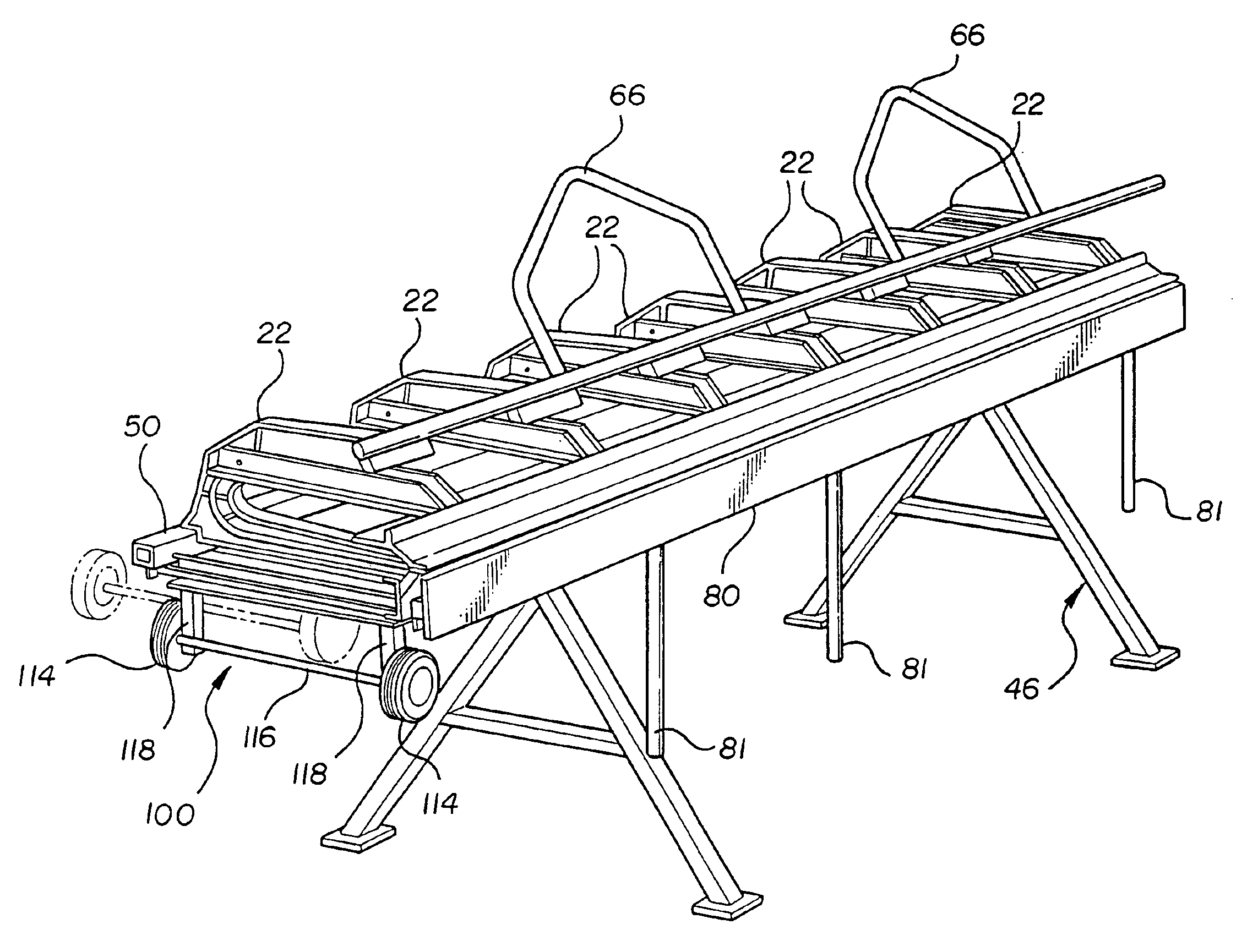
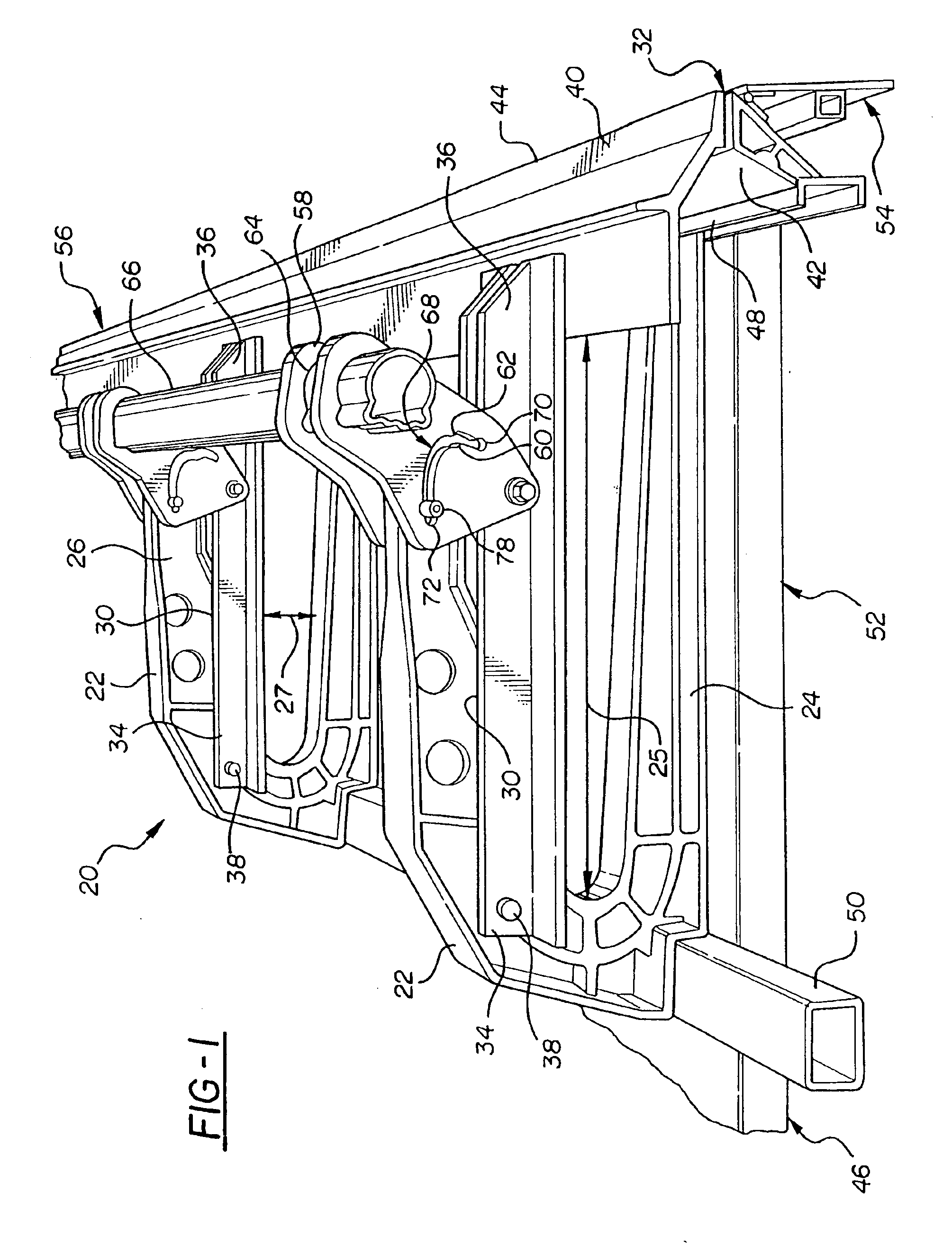
[0026]Referring to the Figures, wherein like numerals indicate like or corresponding parts throughout the several views, a sheet bending brake assembly for securing a work piece 28 is generally shown at 20 in FIG. 1.

[0027]The sheet bending brake assembly 20 includes a clamping member 22 having a lower leg 24 extending therefrom. The clamping member 22 is generally a C-shaped frame member and has an upper leg 26 extending therefrom. As seen in FIG. 1, a plurality of longitudinally spaced clamping members 22 form the assembly 20 and allow for engaging differently sized work pieces 28, as will be described below. However it is to be understood that any number of clamping members 22 may be utilized with the subject invention. FIGS. 5 through 7 illustrate a single clamping member 22 that forms the sheet bending brake assembly 20. It should be appreciated that each of the frame members is substantially identical. Preferably, the clamping members 22 are made of lightweight aluminum to faci...


PUM

PropertyMeasurementUnit
distanceaaaaaaaaaa
weightaaaaaaaaaa
lengthsaaaaaaaaaa

Abstract

The subject invention provides a sheet bending brake assembly for securing a work piece. The sheet bending brake assembly includes a clamping member having a lower leg extending therefrom and a pivoting arm pivotally supported by and extending from the clamping member. The pivoting arm defines a clamping area with the lower leg. A base supports the clamping members and provides support to the assembly while moving the pivoting arm between the open position and the clamped position. A guide mechanism reacts between the clamping member and the pivoting arm for moving the pivoting arm between the open position and the clamped position. The guide mechanism has a guide slot with a detent positioned within the guide slot between the first and the second ends for positioning the pivoting arm in an intermediate position to allow for precisely aligning the work piece.

Description

RELATED APPLICATIONS[0001]This application claims priority to provisional patent applications having Ser. Nos. 60 / 267,777 and 60 / 268,191 filed Feb. 9, 2001 and Feb. 12, 2001, respectively.[0002]This application is a continuation of application Ser. No. 10 / 068,408, filed Feb. 6, 2002 now U.S. Pat. No. 6,675,619.BACKGROUND OF THE INVENTION[0003]1. Field of the Invention[0004]The subject invention relates to sheet bending brakes.[0005]2. Description of the Related Art[0006]Sheet bending brakes are used for bending and cutting metal or plastic sheets such as those used for siding on homes and buildings. A typical sheet bending brake functions by clamping a work piece between clamping members and using a hinged bending arm to bend the work piece about the clamping member. These sheet bending brakes allow for the clamping member to move between an open position and a clamped position.[0007]In the use of such brakes, the work piece is often forced out of position as the clamping member is ...

Claims


Application Information

Patent Timeline
Patent Type & Authority Patents(United States)
IPC IPC(8): B21D5/04
CPCB21D5/04
Inventor CLARK, MICHAEL C.
Owner TAPCO INTERNATIONAL CORPORATON
Why Eureka
Try Eureka