Electrical connector assembly

a technology of electrical connectors and connector assemblies, which is applied in the direction of electrical apparatus, coupling contact parts, printed circuits, etc., can solve the problems of inability to ensure the reliability of the electrical connection between the first connector and the second connector is not good, so as to achieve the effect of improving the normal for

Inactive Publication Date: 2005-06-14
HON HAI PRECISION IND CO LTD
View PDF8 Cites 10 Cited by
  • Summary
  • Abstract
  • Description
  • Claims
  • Application Information

AI Technical Summary

Benefits of technology

[0007]Accordingly, an object of the present invention is to provide an electrical connector assembly, which can improve normal force between two connectors thereof.
[0008]In order to achieve the object set forth, an electrical connector assembly in accordance with the present invention comprises a first connector and a second connector matable with the first connector. The first connector includes a first housing and a plurality of first terminals. The first housing comprises a central island defining a groove and a plurality of apertures. The first terminals are respectively retained in corresponding apertures. The second connector comprises a second insulative housing and a plurality of second terminals. The second housing has an elongate tongue portion mating with the groove of the first housing of the first connector. When the first connector connects with the second connector, the second terminals extend into the corresponding apertures and electrically connect with the first terminals. Accordingly, a stable and reliable electrical connection between the first connector and the second connector is established.

Problems solved by technology

When the resiliency of the first terminals reduces, the first terminals withdraw into the mating portion, thereby resulting in ill electrical connection between the two connectors.
As a result, a reliable electrical connection between the first connector and the second connector cannot be assured.

Method used


Image

  • Electrical connector assembly
  • Electrical connector assembly
  • Electrical connector assembly

Examples


Embodiment Construction

[0016]Reference will now be made in detail to the preferred embodiment of the present invention.

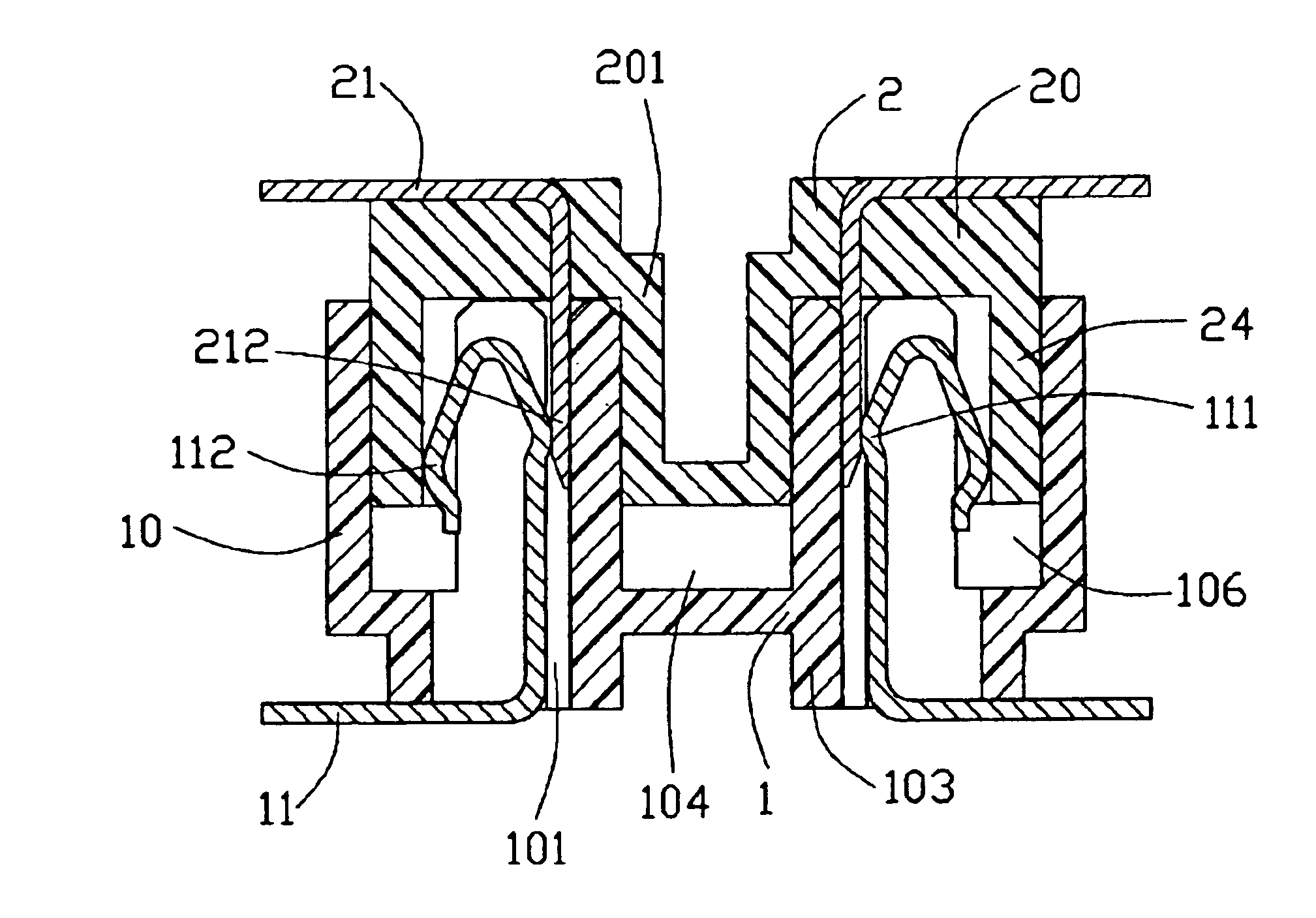
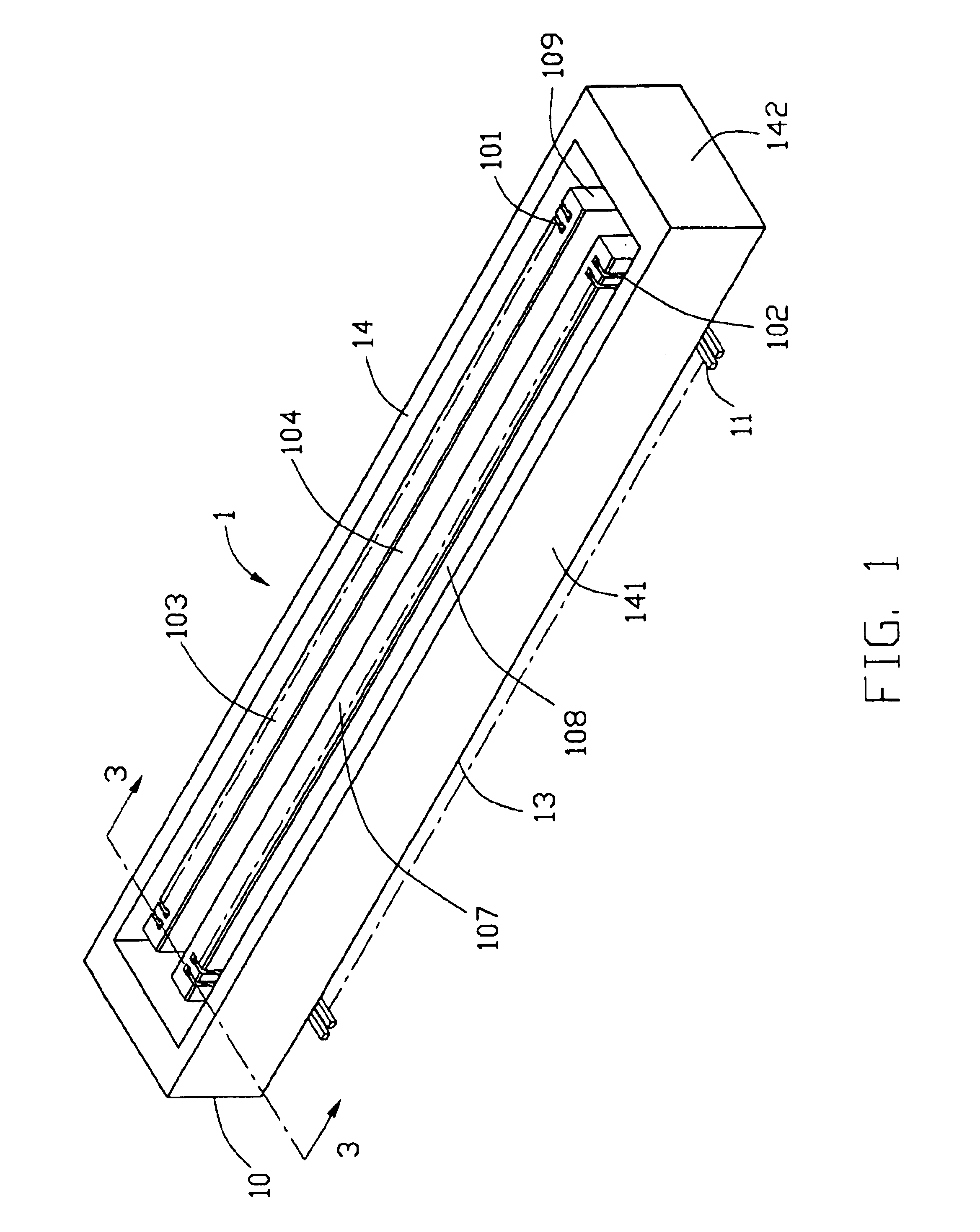
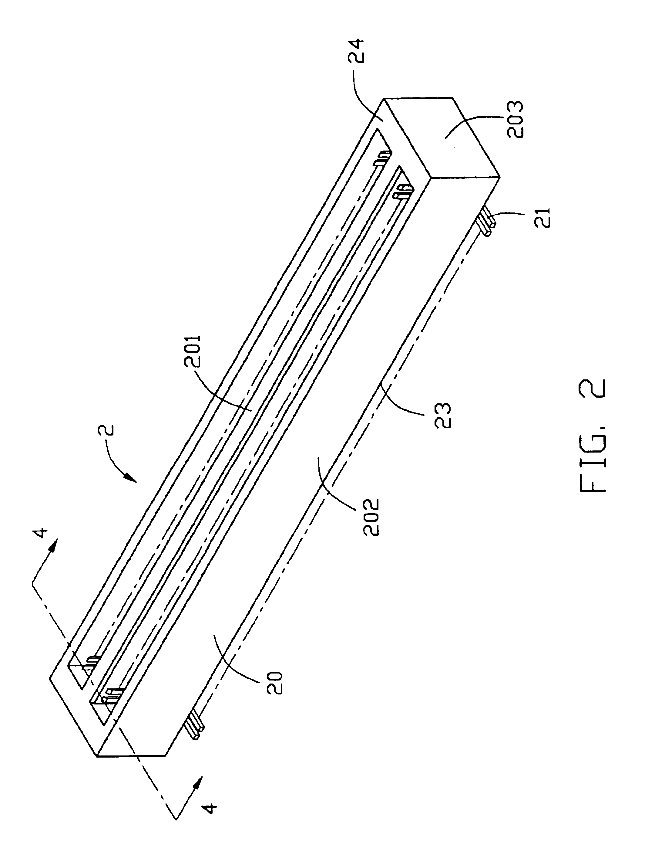
[0017]Referring to FIG. 1 and FIG. 2, an electrical connector assembly consists of a first connector 1 and a second connector 2 matable with the first connector 1.

[0018]Referring to FIG. 1 and FIG. 3, the first connector 1 includes an elongate first insulative housing 10 and a plurality of first terminals 11. The first housing 10 includes a base 13 and a first mating portion 14 extending upwardly from the base 13. The first mating portion 14 comprises a pair of opposite longitudinal walls 141, a pair of opposite lateral walls 142 and formed a receiving space 106 between the longitudinal wall 141 and lateral walls 142. In the center of the receiving space 106, a central island 103 extends upwardly from the first base 13. The central island 103 comprises a top surface 107, a pair of side surfaces 108, a pair of end surfaces 109, and a recess 104 defined therein. A plurality of terminal pass...


PUM


Abstract

An electrical connector assembly for connecting one printed circuit board to another printed circuit board comprises a first connector (1) and a second connector (2). The first connector includes a first insulative housing (10) and a number of first terminals (11). The first insulative housing has an elongate central island (103) with a recess (104) therein, and comprising a number of apertures (101). The first terminals are received in corresponding apertures. The second connector includes a second insulative housing (20) and a number of second terminals (21). The second insulative housing has a tongue portion (201) mating with the recess of the first housing. When the first connector mates with the second connector, the second terminals electrically connect with the first terminals by extending into the apertures respectively.

Description

BACKGROUND OF THE INVENTION[0001]1. Field of the Invention[0002]The present invention generally relates to an electrical connector assembly, and more particularly to an electrical connector assembly for being mounted on two printed circuit boards.[0003]2. Description of Related Art[0004]Board to board electrical connector assembly, consisting of two electrical connectors mounted on nearly parallel printed circuit boards to be connected together, is known in the art. Generally, connector assembly is used for signal transmission between two printed circuit boards.[0005]A connector assembly disclosed in U.S. Pat. No. 6,338,630 comprises matable first and second connectors. The first connector comprises a first insulative housing and a plurality of first terminals received in the first housing. The first housing includes a mating portion and a central island extending upwardly from a base portion of the first housing. The first terminals are retained in the central island, and the conta...

Claims


Application Information

Patent Timeline
Patent Type & Authority Patents(United States)
IPC IPC(8): H01R13/26H01R13/02H01R12/18
CPCH01R12/725H01R13/26
Inventor ZHANG, CHI
Owner HON HAI PRECISION IND CO LTD
Why Eureka
Try Eureka