Positional deviation correction using reference and relative correction values in bi-directional printing

a technology of position deviation and correction value, applied in the field of image printing, can solve the problems of deviation in printing position between forward and reverse printing passes in the main scanning direction, no correction of deviation in other ink colors, and little consideration of positional deviation between forward and reverse printing passes, so as to improve image quality and alleviate the effect of printing positional deviation

Inactive Publication Date: 2005-06-21
SEIKO EPSON CORP
View PDF16 Cites 21 Cited by
  • Summary
  • Abstract
  • Description
  • Claims
  • Application Information

AI Technical Summary

Benefits of technology

[0008]An object of the present invention is to improve image quality by alleviating printing positional deviation arising between forward and reverse passes in the main scanning direction during bi-directional printing.

Problems solved by technology

A problem that readily arises in bi-directional printing is that of deviation in printing position between forward and reverse printing passes in the main scanning direction caused by backlash in the main scanning drive mechanism and warping of the platen that supports the print media.
However, in the case of bi-directional printing using multilevel printers, little consideration has been given to positional deviation arising between forward and reverse printing passes.
Other problems include that while deviation may be corrected with respect to a particular one of the multiple colored inks, there is no correction of deviation in other ink colors.
As a result, the deviation correction provides little improvement in the quality of the color image.

Method used


Image

  • Positional deviation correction using reference and relative correction values in bi-directional printing
  • Positional deviation correction using reference and relative correction values in bi-directional printing
  • Positional deviation correction using reference and relative correction values in bi-directional printing

Examples


first embodiment (

C. First Embodiment (First Example of Correcting Positional Deviation between Nozzle Rows):

[0090]FIG. 11 is a flow chart of the process steps in a first embodiment of the invention. In step S1, the printer 20 is assembled on the production line, and in step S2 an operator sets relative correction values for correcting positional deviation in the printer 20. In step S3 the printer 20 is shipped from the factory, and in step S4, the purchaser of the printer 20 prints after setting a reference correction value for correcting positional deviation during use. Steps S2 and S4 will be each described in more detail below.

[0091]FIG. 12 is a flow chart showing details of the step S2 of FIG. 11. In step S11, a test pattern is printed to determine relative correction values. FIG. 13 shows an example of such a test pattern. The test pattern consists of the six vertical lines LK, LC, LLC, LM, LLM, LY formed in the sub-scanning direction y in the six colors K, C, LC, M, LM, Y. The six lines were p...

second embodiment (

D. Second Embodiment (Second Example of Correcting Positional Deviation between Nozzle Rows):

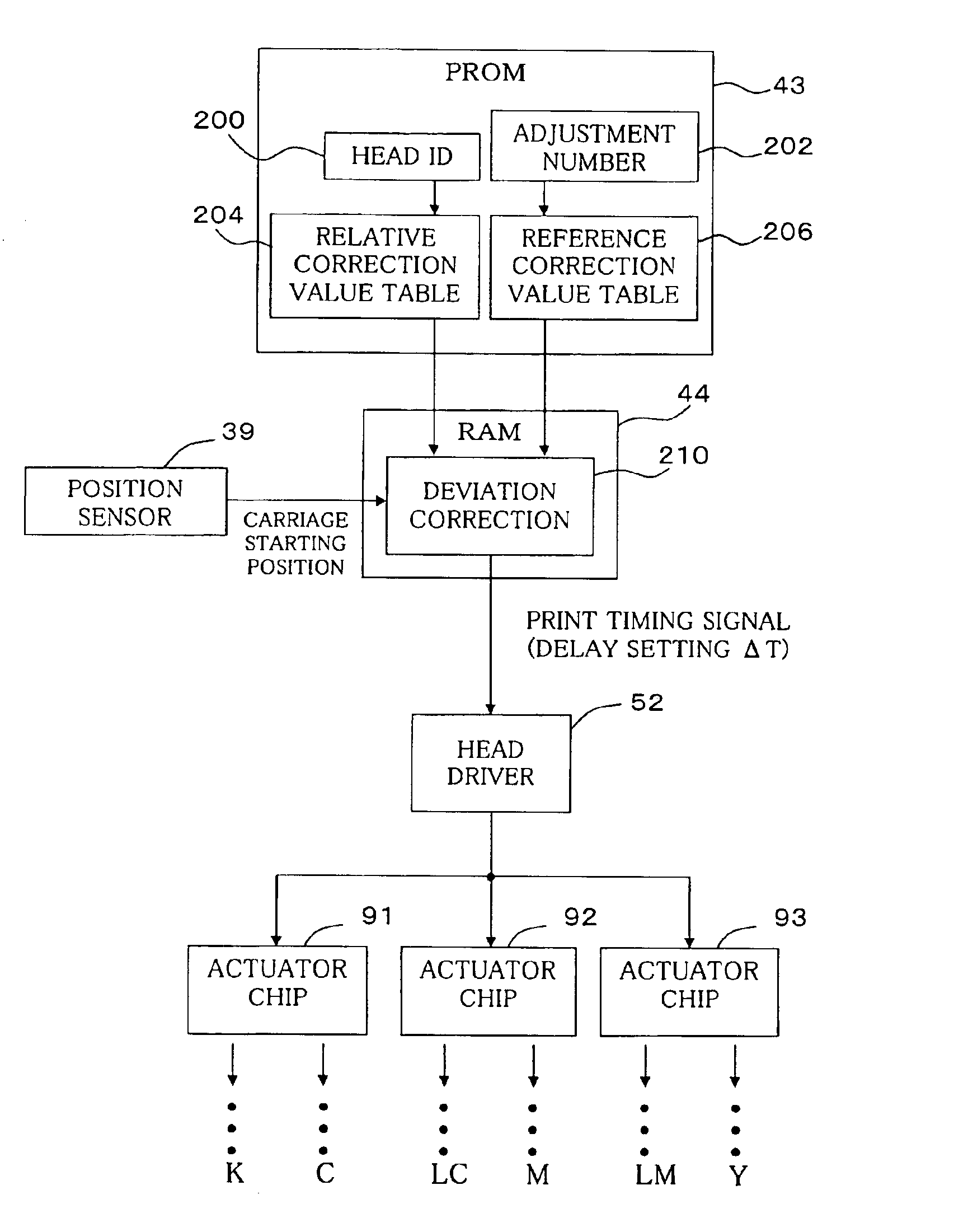
[0121]FIG. 21 is a block diagram of the main configuration involved in the correction of deviation during bi-directional printing in the second embodiment. The difference compared to the configuration of FIG. 17 is that each of the actuator chips 91, 92 and 93 is provided with its own, independent head drive circuit 52a, 52b and 52c. Thus, printing timing signals from the deviation correction section 210 can be independently applied to the head drive circuits 52a, 52b and 52c. Therefore, correction of positional deviation during bi-directional printing can also be effected on an actuator chip by chip basis.

[0122]In this second embodiment, too, the row K of black ink nozzles of the first actuator chip 91 is used as the reference. Thus, as in the first embodiment, the reference correction value is determined using a test pattern printed using the the row K of black ink nozzles.

[0123]In this se...

third embodiment (

E. Third Embodiment (Correction of Positional Deviation Between Dots of Different Sizes):

[0129]In the first and second embodiments described in the foregoing, printing positional deviation between rows of nozzles is corrected. In the third embodiment described below, printing positional deviation between dots of different sizes is corrected.

[0130]FIGS. 22(a) and 22(b) illustrate the waveform of a base drive signal ODRV that is supplied from the head drive circuit 52 (FIG. 2) to the print head 28. During a forward pass, in a single pixel period, the base drive signal ODRV generates a large dot waveform W11, a small dot waveform W12 and a medium dot waveform W13, in that order. And during a reverse pass, in a single pixel period, a medium dot waveform W21, a small dot waveform W22 and a large dot waveform W23 are generated, in that order. During a forward pass or a reverse pass, any one of the three waveforms can be selectively used to print a large, small or medium dot at a pixel pos...


PUM


Abstract

In the bi-directional printing, a reference correction value is set for correcting printing positional deviation arising between forward and reverse main scanning passes with respect to specific reference dots. An adjustment value is determined, using at least the reference correction value, to reduce printing positional deviation arising between forward and reverse main scanning passes. The printing positional deviation between forward and reverse main scanning passes is adjusted using the adjustment value. In a first adjustment mode, the adjustment value is determined by correcting the reference correction value with a relative correction value prepared beforehand for correcting the reference correction value.

Description

CROSS-REFERENCE TO RELATED APPLICATIONS[0001]This is a continuation application of parent U.S. application Ser. No. 09 / 497,168, filed Feb. 3, 2000 now U.S. Pat. No. 6,692,096. This application is based upon and claims the benefit of priority from Japanese Patent Application No. 11-032163, filed Feb. 10, 1999 and Japanese Patent Application No. 11-231269, filed Aug. 18, 1999, and the entire contents of the parent application and both Japanese applications are hereby incorporated herein by reference.BACKGROUND OF THE INVENTION[0002]1. Field of the Invention[0003]This invention relates to a technology for printing images on a print medium using a bi-directional reciprocating movement in a main scanning direction. The invention particularly relates to a technology for correcting printing positional deviation between forward and reverse passes.[0004]2. Description of the Related Art[0005]In recent years color printers that emit colored inks from a print head are coming into widespread us...

Claims


Application Information

Patent Timeline
Patent Type & Authority Patents(United States)
IPC IPC(8): B41J19/14B41J2/21B41J19/00B41J19/20B41J2/16B41J2/01B41J2/51B41J19/18
CPCB41J2/2128B41J2/2135B41J19/145B41J19/202B41J2202/17B41J19/142
Inventor OTSUKI, KOICHIYONEKUBO, SHUJITAYUKI, KAZUSHIGEMITSUZAWA, TOYOHIKO
Owner SEIKO EPSON CORP
Why Eureka
Try Eureka