Cable terminal

Inactive Publication Date: 2005-06-21
CABLESAT INT
View PDF6 Cites 30 Cited by
  • Summary
  • Abstract
  • Description
  • Claims
  • Application Information

AI Technical Summary

Benefits of technology

[0006]The primary objective of the present invention is to provid

Problems solved by technology

The work of engaging the conventional t

Method used


Image

  • Cable terminal
  • Cable terminal
  • Cable terminal

Examples


Example

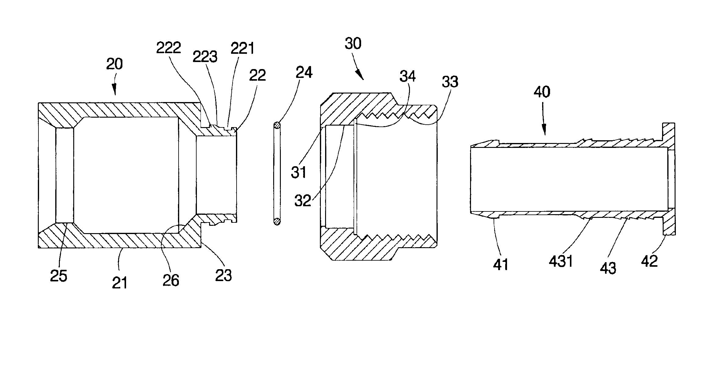
[0013]As shown in FIG. 3, a cable terminal 10 of the preferred embodiment of the present invention comprises a base 20, an outer member 30 and an engaging member 40.

[0014]The base 20 is a round tube with a large portion 21, a small portion 22 and an annular wall 23 between the large portion 21 and the small portion 22. The small portion 22 has, from a distal end, an annular slot 221, a tilting guiding flat 223 and an annular protrusion 222 on an outer surface thereof. A ring 24 is fitted to the small portion 22 and rested in the slot 221. The large portion 21 has a first engaging portion 25 at an interior surface thereof and a stop flat 26 beside the first engaging portion 25 and adjacent to the small portion 22.

[0015]The outer member 30 is a hexagonal tube with a three-order round hole, wherein on a sidewall of the hole is a first protrusion portion 31, from an end thereof, a second protrusion portion 32, a stop portion 34 and a thread 33. A diameter of the hoe at the first protrus...


PUM


Abstract

A cable terminal has a base having a hole, a large portion, a small portion and an annular wall therebetween. The small portion has an annular protrusion and a tilted guiding flat beside the annular protrusion. An outer member has a hole and on a sidewall of the hole is a first protrusion portion, a second protrusion portion, a stop portion and a thread in sequence. The outer member is fitted to the smaller portion of the base with the first protrusion portion crossing the guiding flat and engaged with the annular protrusion. An engaging member is received in both of the base and the outer member and has a plate against the stop portion of the outer member to move the outer member toward the base, in which the first protrusion portion is moved to where between the annular flat and the annular protrusion.

Description

BACKGROUND OF THE INVENTION[0001]1. Field of the Invention[0002]The present invention relates generally to a cable, and more particularly to a cable terminal.[0003]2. Description of the Related Art[0004]FIG. 1 and FIG. 2 show a conventional cable terminal 60, which has a base 61, an outer member 62 and an engaging member 63. The base 61 is a round tube fitted to the cable. The outer member 62 is a hexagonal tube with a round hole and on a sidewall of the hole is a thread 621. An end of the outer member 62 is rested on an end of the base 61. The engaging member 63, which is a round tube, is inserted into both of the base 61 and the outer member 62 and has a protrusion 631 at an end thereof to stop the outer member 62. The engaging member 63 has an end in the base 61 inserted into a cable between an insulating layer and an isolating layer (not shown). In connection with an electric product, such as television, the outer member 61 is turned to tighten or loose the terminal.[0005]Howeve...

Claims


Application Information

Patent Timeline
IPC IPC(8): H01R9/05
CPCH01R9/0518
Inventor LI, JACKIE
Owner CABLESAT INT
Why Eureka
Try Eureka