Cover for electrical switch

a cover and switch technology, applied in the field of electrical switches, can solve the problems of affecting the operation of the switch handle, and the size of the toggle or the rocker portion of the switch is too small, so as to achieve the effect of enlarge the size of the switch handl

Inactive Publication Date: 2005-06-21
HUBBELL INC
View PDF23 Cites 18 Cited by
  • Summary
  • Abstract
  • Description
  • Claims
  • Application Information

AI Technical Summary

Benefits of technology

[0009]Accordingly, an object of the present invention is to provide a cover for an electrical switch that can effectively cover u

Problems solved by technology

Both toggle switches and rocker switches have been limited in some applications and for some users in that the size of the toggle or the rocker portion of the switch is too small.
They also do not stand out far from the wall, which in some instances is disadvantageous.
Moreover, in some instances the toggle or the

Method used


Image

  • Cover for electrical switch
  • Cover for electrical switch
  • Cover for electrical switch

Examples


Embodiment Construction

[0095]Reference will now be made in detail to the presently preferred embodiments of the invention as illustrated in the accompanying drawings, in which like reference characters designate like or corresponding parts throughout the drawings. It should be noted, however, that the invention in its broader aspects is not limited to the specific details, representative devices, and illustrative examples shown and described in this section in connection with the preferred embodiments.

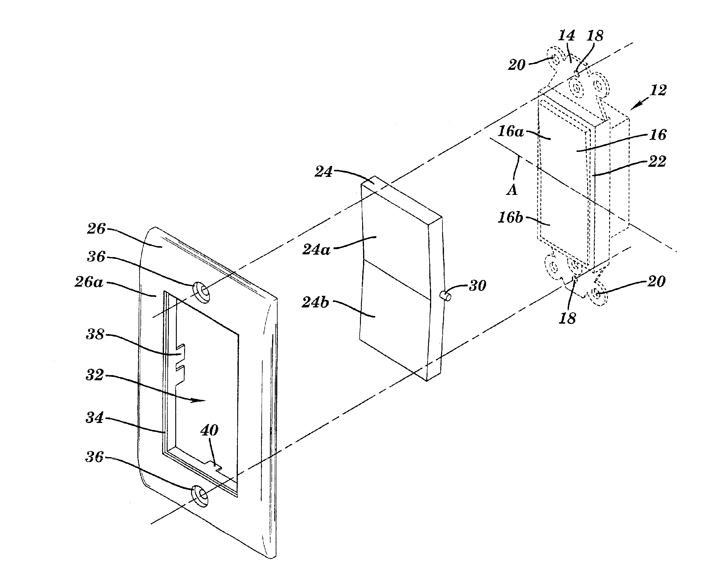
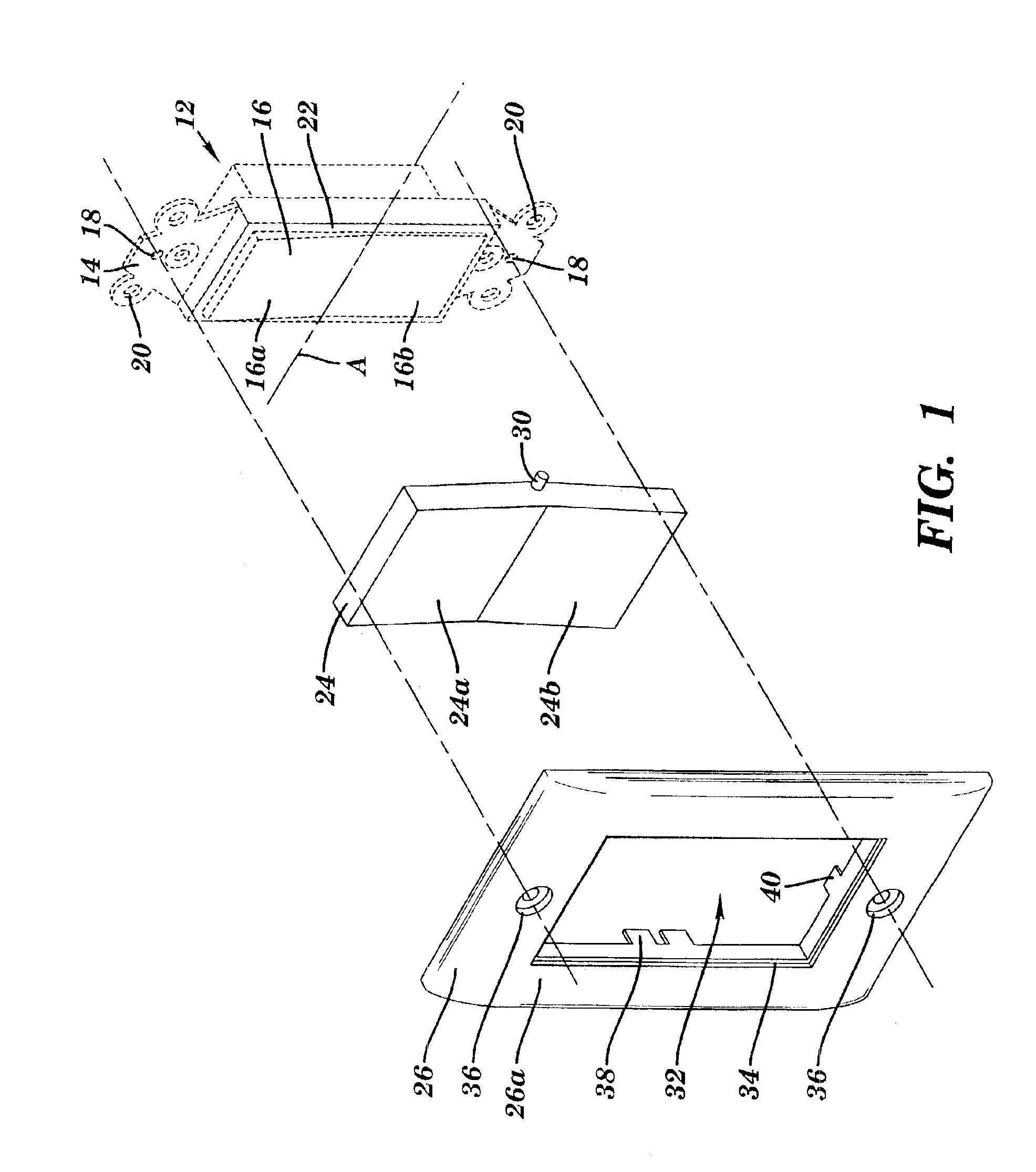
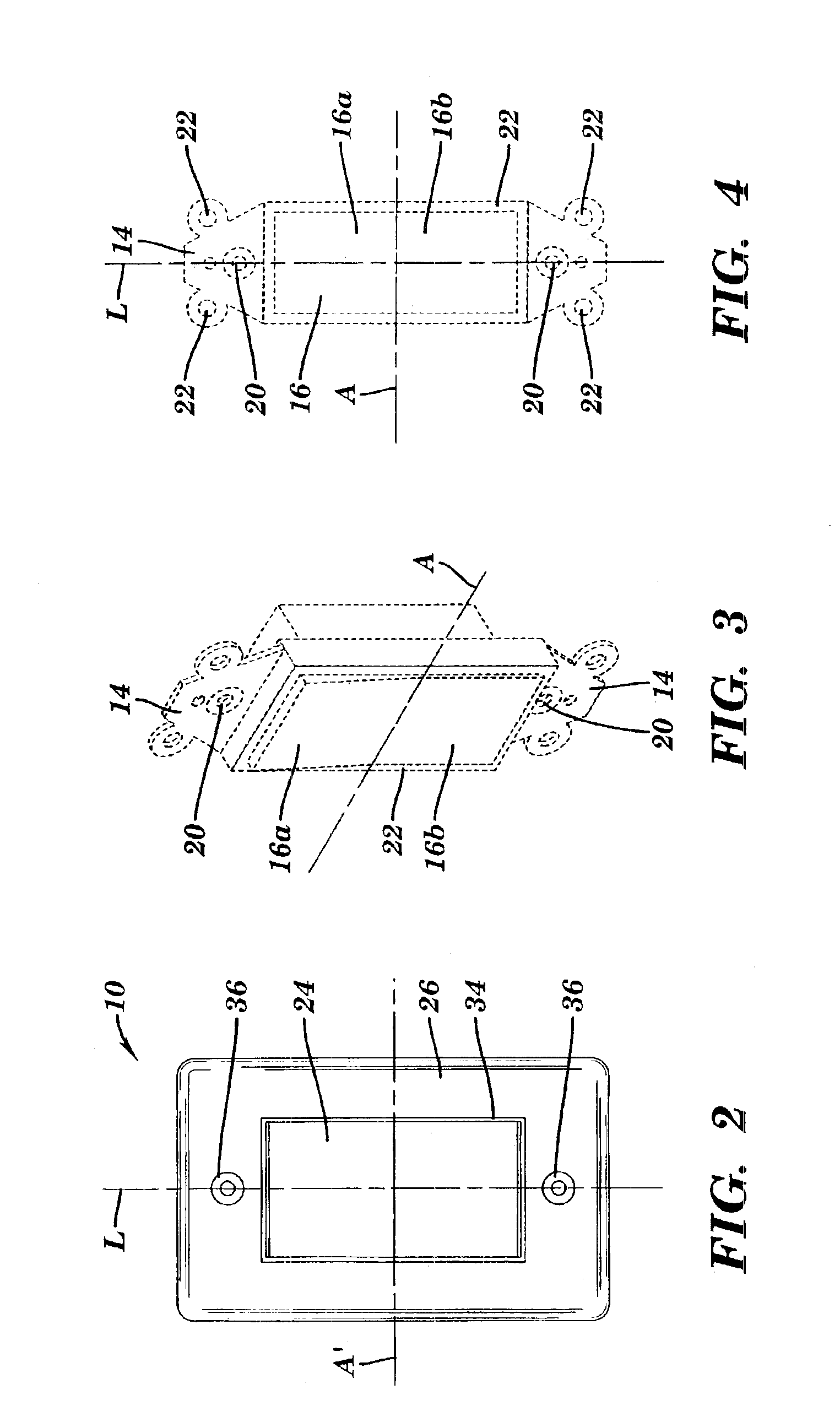
[0096]In accordance with the invention, a cover is provided for an electrical switch. The electrical switch includes a yoke and a switch handle. For purposes of this aspect of the invention, the preferred form of electrical switch is the so-called rocker switch design. In accordance with this aspect of the invention, the electrical switch includes a handle cover sized and shaped to substantially conform to and fit over the switch handle of the electrical switch. The handle cover has rotation points disposed ...


PUM


Abstract

A cover for an electrical switch, wherein the electrical switch includes a yoke and a switch handle. In a first embodiment, which is particularly well suited for rocker-type switches, the cover comprises a handle cover sized and shaped to substantially conform to and fit over the switch handle. The handle cover has rotation points disposed parallel to an axis and including two planar surfaces, each of the planar surfaces being parallel to and passing through the axis. The cover also comprises a cover plate having a switch handle aperture for receiving the handle cover. The cover plate includes contact points for receiving the rotation points in movable relation. In an alternative embodiment, which is well suited for toggle switch applications, a cover is provided for an electrical switch, wherein the cover comprises a handle cover assembly including a handle cover member sized and shaped to substantially conform to and fit over the switch handle and a face member in which the handle cover member is slidably disposed. The handle cover member includes a handle cover which forms a cavity for receiving the switch handle. The cover further includes a cover plate having a handle cover aperture for receiving the handle cover assembly.

Description

CROSS REFERENCE TO RELATED APPLICATIONS[0001]This application is a divisional application of a divisional application by Shotey, et al. entitled “COVER FOR ELECTRICAL SWITCH”, Ser. No. 10 / 055,123, filed Jan. 22, 2002 now U.S. Pat. No. 6,586,694; which is a divisional of application by Shotey, et al. entitled “COVER FOR ELECTRICAL SWITCH”, Ser. No. 09 / 479,805, filed Jan. 8, 2000 now U.S. Pat. No. 6,384,354, which is incorporated herein by reference.BACKGROUND OF THE INVENTION[0002]1. Field of the Invention[0003]The present invention relates generally to electrical switches for switching electrical appliances such as lights, fans, etc. on and off and, more specifically, to covers for electrical switches.[0004]2. Description of the Related Art[0005]Electrical switches such has those used in residential and commercial buildings to turn on and off lights, fans, etc. have been used for years and have undergone relative few design changes. Although various designs have been used in the pas...

Claims


Application Information

Patent Timeline
IPC IPC(8): H02G3/14H01H23/04H01H23/14
CPCH01H23/04H02G3/14H01H23/148
Inventor SHOTEY, MICHAELMCCONNAUGHY, MICHAELMALTBY, EDGAR W.
Owner HUBBELL INC
Why Eureka
Try Eureka