Method and apparatus for pre-computing and using placement costs within a partitioned region for multiple wiring models

a technology of partitioning region and placement cost, which is applied in the field of method and apparatus for precomputing and using placement cost within partitioned region for multiple wiring models, can solve the problems of large area, poor performance, and estimate the cost of placement, and achieve the effect of improving placement cos

Inactive Publication Date: 2005-06-21
CADENCE DESIGN SYST INC
View PDF90 Cites 10 Cited by
  • Summary
  • Abstract
  • Description
  • Claims
  • Application Information

AI Technical Summary

Benefits of technology

[0046]Next, the placement method uses an optimization algorithm that iteratively modifies the placement configuration in the received IC regions, in order to improve the placement cost. Different embodiments of the invention use different optimization techniques, such as annealing, local optimization, KLFM, tabu search, etc.
[0047]After each iterative modification during optimization, the placement configuration is re-calculated by repeating the cost-calculating operations described above for...

Problems solved by technology

A poor placement configuration not only can consume a large area, but it also can make routing difficult and result in poor performance.
This method quickly generates an estimate of the wirelength cost of a placement.
Heuristic techniques are often used to select the R Steiner points and construct the Steiner tree, since these problems cannot be solved in pol...

Method used


Image

  • Method and apparatus for pre-computing and using placement costs within a partitioned region for multiple wiring models
  • Method and apparatus for pre-computing and using placement costs within a partitioned region for multiple wiring models
  • Method and apparatus for pre-computing and using placement costs within a partitioned region for multiple wiring models

Examples


Embodiment Construction

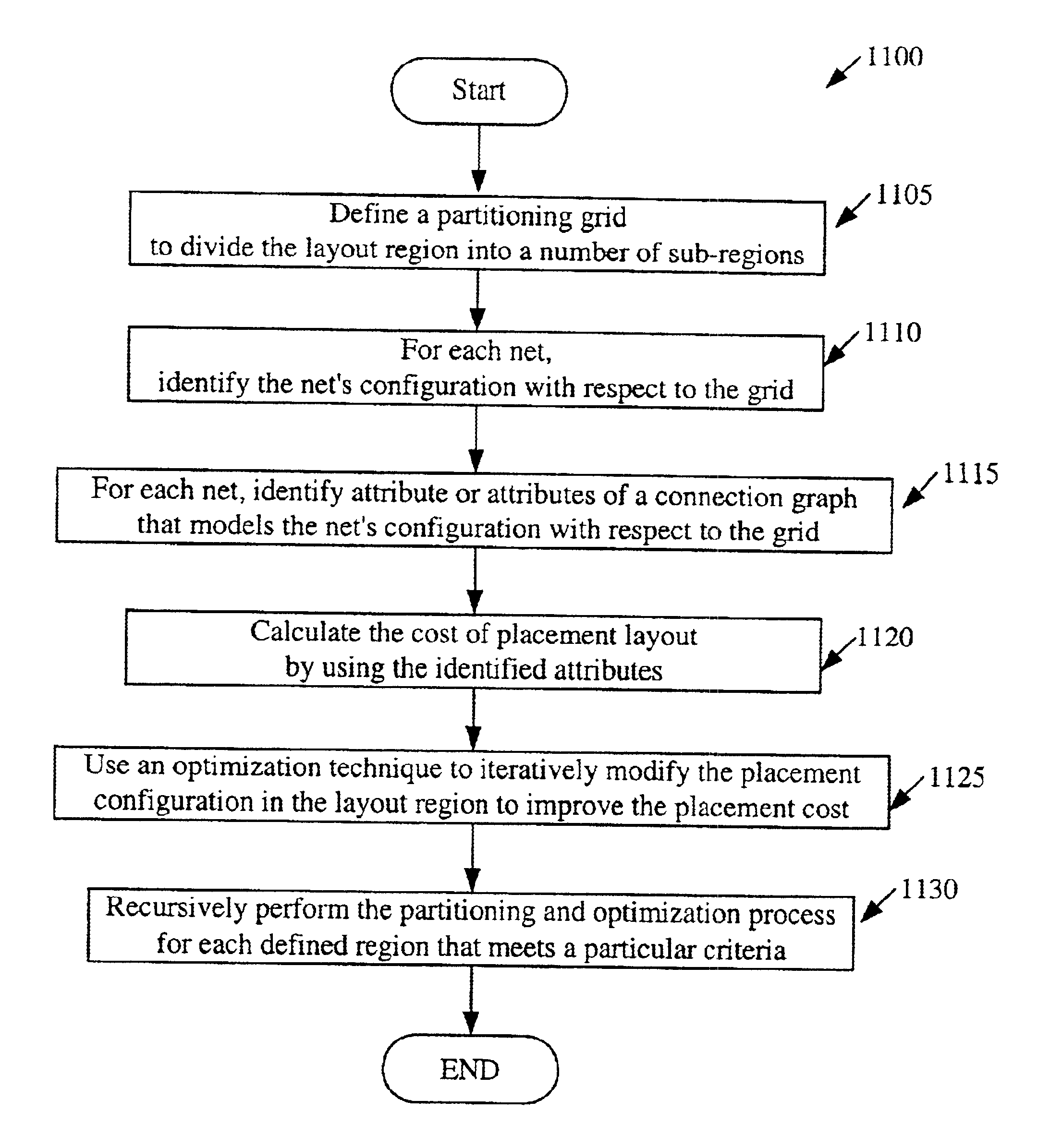
[0097]The invention is directed towards recursive partitioning placement method and apparatus. In the following description, numerous details are set forth for purpose of explanation. However, one of ordinary skill in the art will realize that the invention may be practiced without the use of these specific details. In other instances, well-known structures and devices are shown in block diagram form in order not to obscure the description of the invention with unnecessary detail.

[0098]Several embodiments of the invention's recursive partitioning technique are described below. However, before discussing these embodiments, several diagonal wiring architectures that can be used in conjunction with these embodiments are described in Section I.

I. Diagonal Wiring Architecture

[0099]Some embodiments of the invention calculate the cost of placement configurations for IC layouts that have diagonal interconnect lines (i.e., diagonal wiring). In some of these embodiments, the IC layouts not on...


PUM


Abstract

One embodiment of the invention is a recursive partitioning method that places circuit elements in an IC layout. This method initially defines a number of partitioning lines that divide an IC region into several sub-regions (also called slots). For a net in the region, the method then identifies the set of sub-regions (i.e., the set of slots) that contain the circuit elements (e.g., the pins of circuit modules) of that net. The set of sub-regions for the net represents the net's configuration with respect to the defined partitioning lines. Next, the placement method identifies attribute or attributes of a connection graph that models the net's configuration with respect to the partitioning lines. The connection graph for each net provides a topology of interconnect lines that connect the slots that contain the net's circuit elements. According to some embodiments of the invention, the connection graph for each net can have edges that are completely or partially diagonal.

Description

CLAIM OF BENEFIT TO PRIOR APPLICATIONS[0001]This application is a continuation application of U.S. patent application entitled “Recursive Partitioning Placement Method and Apparatus,” filed on Dec. 6, 2000, and having the Ser. No. 09 / 732,181.FIELD OF THE INVENTION[0002]The invention is directed towards method and apparatus for pre-computing and using placement costs within a partitioned region for multiple wiring models.BACKGROUND OF THE INVENTION[0003]An integrated circuit (“IC”) is a semiconductor device that includes many electronic components (e.g., transistors, resistors, diodes, etc.). These components are often interconnected to form multiple circuit components (e.g., gates, cells, memory units, arithmetic units, controllers, decoders, etc.) on the IC. The electronic and circuit components of IC's are jointly referred to below as “components.”[0004]An IC also includes multiple layers of metal and / or polysilicon wiring (collectively referred to below as “metal layers”) that in...

Claims


Application Information

Patent Timeline
IPC IPC(8): G06F17/50G11B7/085G06F9/45
CPCG06F17/5072G06F17/5077G11B7/08582G06F30/392G06F30/394G06F2111/06
Inventor TEIG, STEVENGANLEY, JOSEPH L.
Owner CADENCE DESIGN SYST INC
Why Eureka
Try Eureka