Software development methodology including creation of focus areas and decomposition of same to create use cases

a software development and focus area technology, applied in the field of computer-assisted software engineering, can solve the problems of software developers, use cases still have drawbacks, and much lower abstraction levels

Inactive Publication Date: 2005-06-21
UNISYS CORP
View PDF4 Cites 29 Cited by
  • Summary
  • Abstract
  • Description
  • Claims
  • Application Information

AI Technical Summary

Benefits of technology

[0008]According to the method of the present invention, requirements for the software are specified for the top-level focus area. When the next-lower-level focus area is generated, the requirements specified at a previous level are propagated down to the next level. The software developer is then able to consider these requirements and how they would apply to the lower-level focus area. This consideration may yield a new set of requirements based on the original requirements, where the new requirements are directed to particular development issues that pertain to the lower-level focus area. These new requirements, in turn, may be further propagated to lower-level focus areas. This process of...

Problems solved by technology

The disadvantage to this traditional approach is that it requires the software developer to model the development process in terms of the low-level actions that a computer can be instructed to perform, rather than in terms of the contemplated use of the software by actual business users.
However, use cases still have the drawback of being, in many situations, at a much lower level of abstraction than the requirements for which the software is designed.
However, the management's vision for such a system is not likely to be at a level of detail that includes all of the exemplary uses of the system (e.g., scheduling a personal appointment, sch...

Method used


Image

  • Software development methodology including creation of focus areas and decomposition of same to create use cases
  • Software development methodology including creation of focus areas and decomposition of same to create use cases
  • Software development methodology including creation of focus areas and decomposition of same to create use cases

Examples


Embodiment Construction

Overview

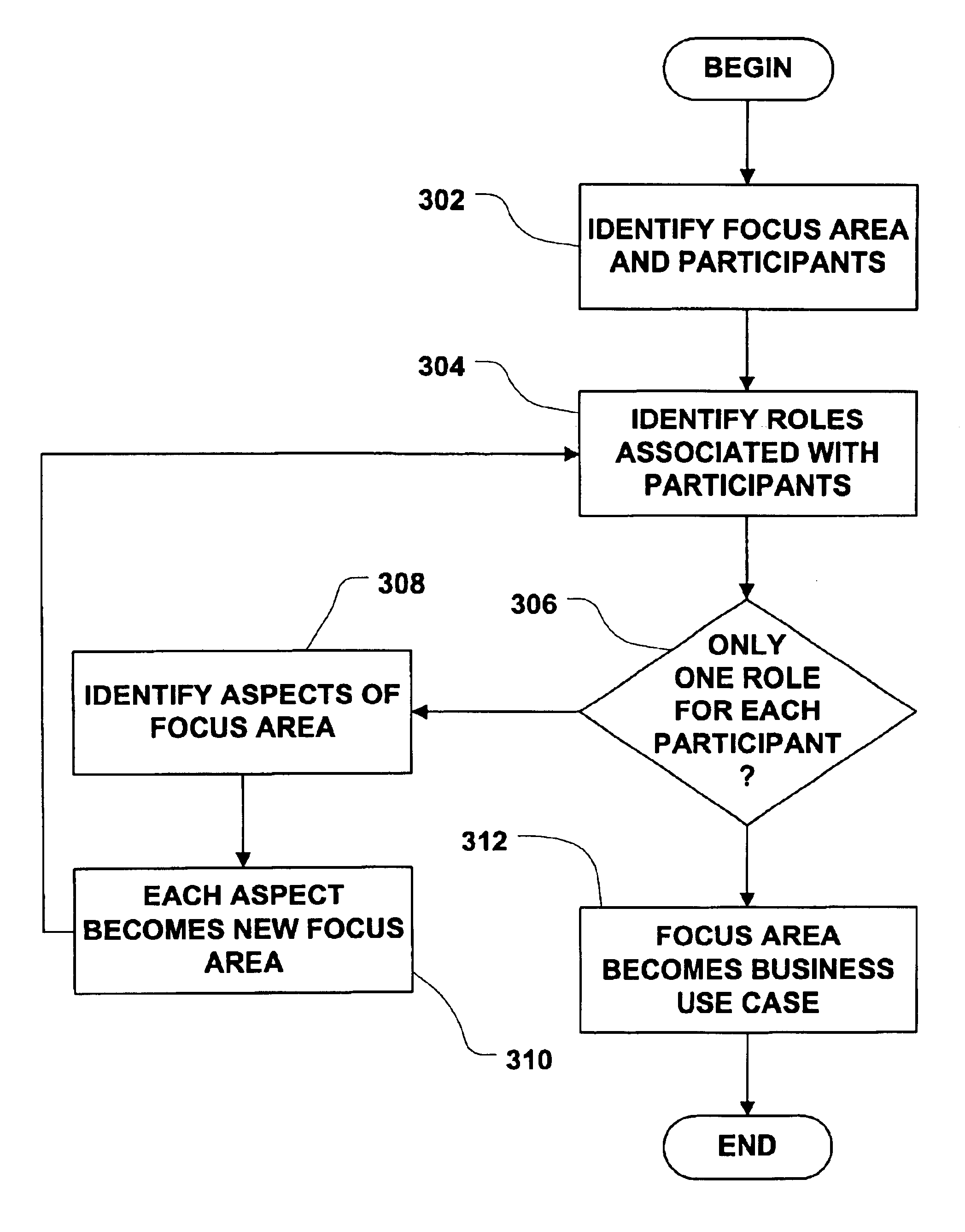
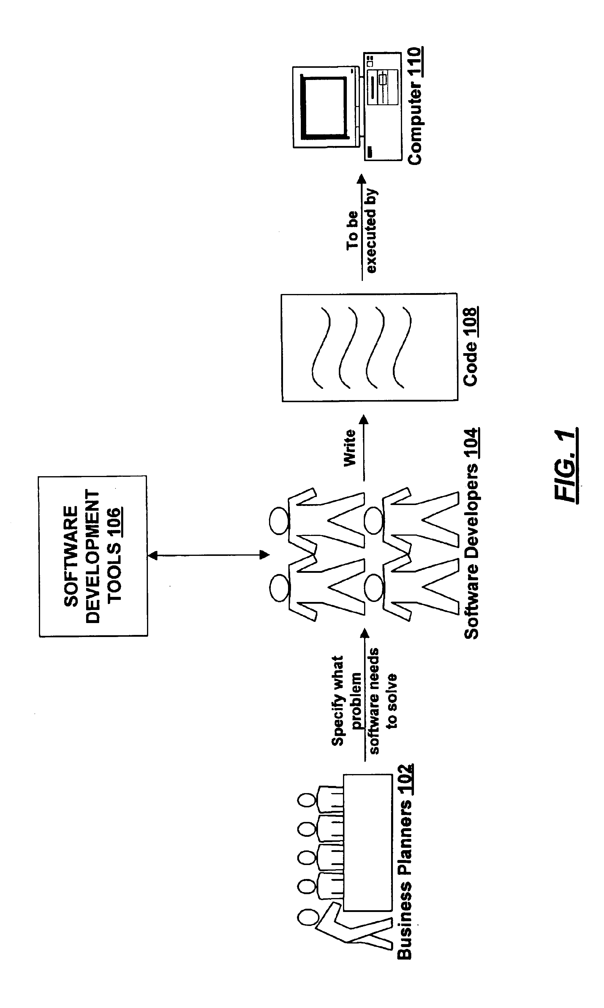
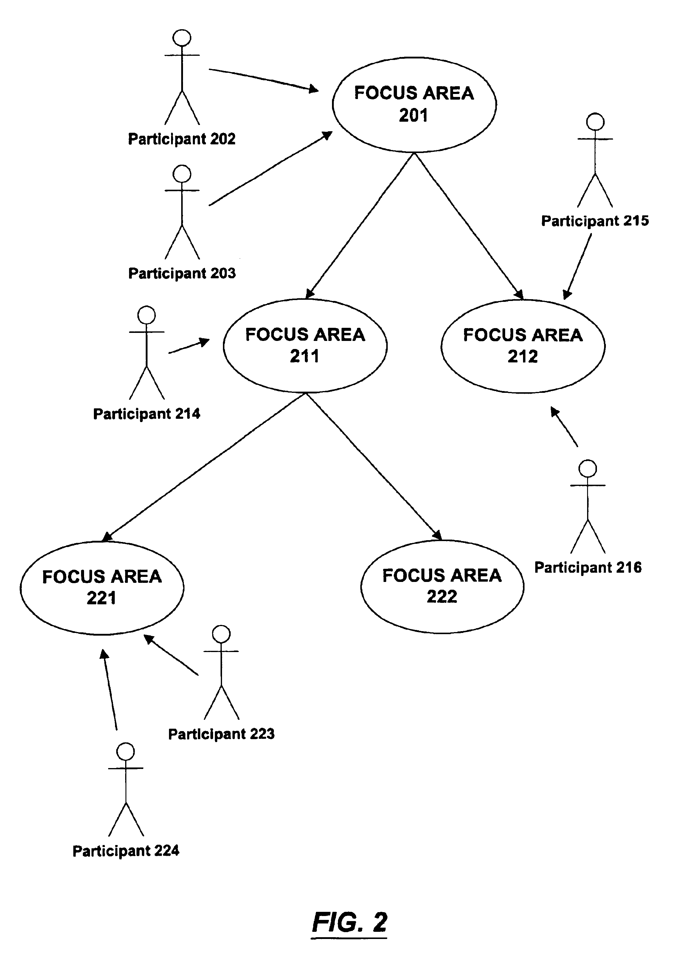
[0019]When the software industry was in its infancy, software was typically envisioned, designed, and written by programmers. In general, programmers would attempt to understand a problem that existed in the business world, and would then write software to solve the problem as they perceived it. As the software development industry has matured, the process of software development has shifted from a focus on what problems software developers are able to solve to a focus on the processes that business people need to automate. The present invention provides a methodology for developing software based on a business process by decomposing the business process level by level until the process has been decomposed into the low-level constructs needed by programmers to implement the software. This methodology helps to prevent important aspects of the business process from being lost in the course of translating the high-level vision of a business process into the low-level constructs...


PUM


Abstract

A methodology for creating Unified Modeling Language (UML) use cases by decomposing a business process into one or more levels of focus areas. A top-level focus area defines the business process and a set of participants therein. The top-level focus area is decomposed by identifying divisible aspects or subsets of the business process, and by identifying the various roles played by the participants. The result of this decomposition is one or more sub-focus areas, each having associated therewith a set of participants based on the top-level participants. The focus areas and participants are recursively decomposed level-by-level until a set of bottom-level focus areas is obtained satisfying the condition that each participant has only one role. When this condition is met, the bottom-level focus areas may be modeled as UML business use cases and used to develop software that meets the specified business process.

Description

FIELD OF THE INVENTION[0001]The invention relates generally to the field of computer-assisted software engineering. More particularly, the invention provides a technique for developing software by hierarchically decomposing a set of general requirements for the software and a set of multiple role participants into a set of use cases, where each use case covers the usage of the software by a sub-participant having a single role.BACKGROUND OF THE INVENTION[0002]Fundamentally, a software application is a set of instructions that can be followed by a computer to perform one or more tasks. Traditionally, a software application was designed by identifying the task(s) to be performed and writing instructions to perform those tasks in a programming language, such as C or C++. The disadvantage to this traditional approach is that it requires the software developer to model the development process in terms of the low-level actions that a computer can be instructed to perform, rather than in t...

Claims


Application Information

Patent Timeline
IPC IPC(8): G06F9/44
CPCG06F8/10
Inventor ROSSOMANDO, PHILIP J.
Owner UNISYS CORP
Why Eureka
Try Eureka