Camouflage covering system

Inactive Publication Date: 2005-06-28
LUCKY ZONE DESIGN GRP
View PDF10 Cites 24 Cited by
  • Summary
  • Abstract
  • Description
  • Claims
  • Application Information

AI Technical Summary

Benefits of technology

[0004]The present invention provides advantages and alternatives over the prior art by providing a camouflage system incorporating an arrangement of profile disturbing strip elements disposed selectively in attached relation across a garment surface. The strip elements

Problems solved by technology

While such practices may provide structures with good camouflage protection, such manufacturing techniques are relatively comp

Method used


Image

  • Camouflage covering system
  • Camouflage covering system
  • Camouflage covering system

Examples


Example

[0013]While the invention has been illustrated and will hereinafter be described in connection with certain exemplary and potentially preferred embodiments and practices, it is to be understood that in no event is the invention to be limited to such illustrated and described embodiments and practices. On the contrary, it is intended that the invention shall extend to all alternatives and modifications as may embrace the principles of this invention within the fill spirit and scope thereof.

DESCRIPTION OF THE PREFERRED EMBODIMENT

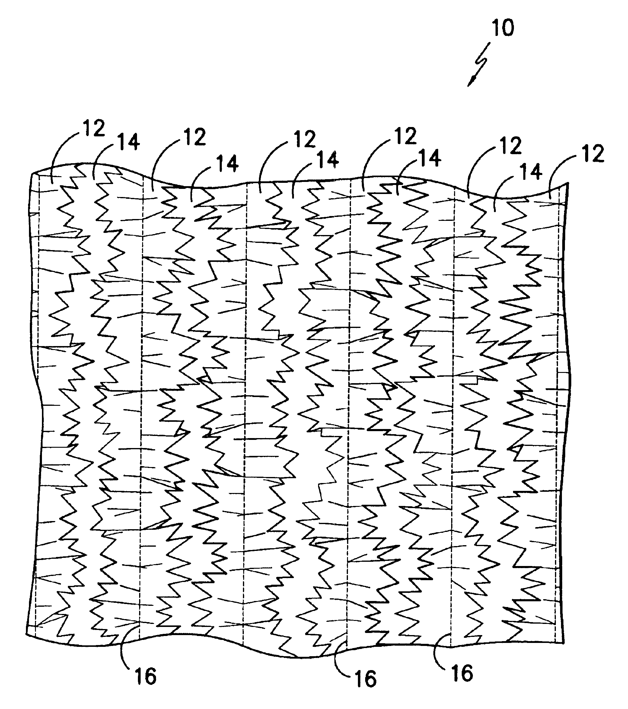
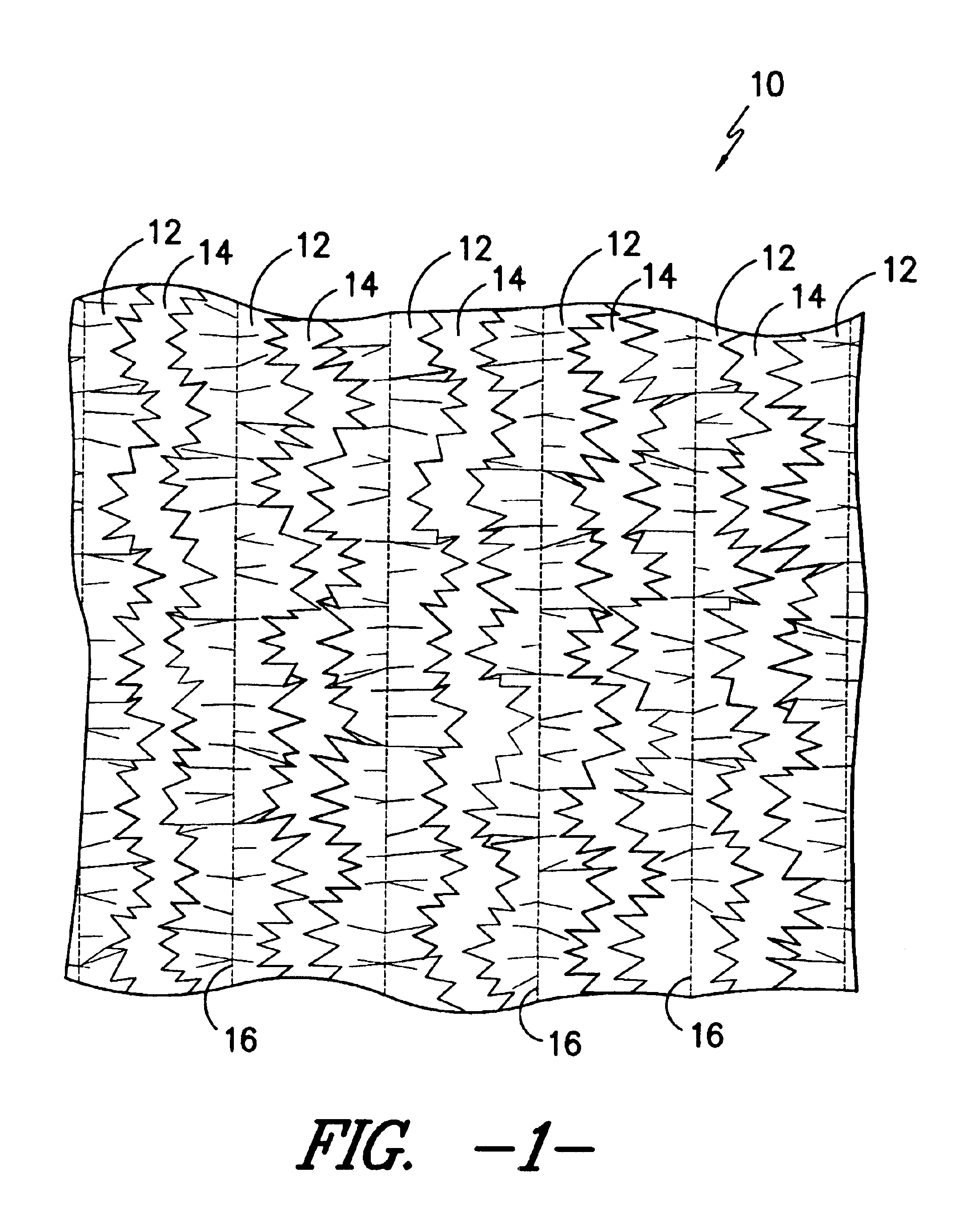
[0014]Reference will now be made to the several figures wherein to the extent possible like reference numerals are used throughout the various views to designate the same feature, material, or relationship. As previously indicated, the camouflage system of the present invention utilizes the selective attachment of the leaf-simulating camouflage strips across panels of fabric forming one or more clothing articles. By way of example only, FIG. 1 illustrates a pa...


PUM


Abstract

A camouflage outer wear garment system including garments incorporating selected patterns of leaf simulating camouflage strips. At least a portion of the camouflage strips include a multiplicity of texture imparting pleats projecting in transverse angled relation to the length direction of the strips. The camouflage strips may be arranged across portions of a jacket, trousers and/or hood for use alone or in combination with other garments.

Description

CROSS-REFERENCE TO RELATED APPLICATION[0001]This application is a continuation-in-part of commonly owned co-pending application Ser. No. 10 / 330,917 filed Dec. 26, 2002 which is a division of application Ser. No. 09 / 982,184 filed Oct. 17, 2001 (now U.S. Pat. No. 6,499,141) which claims benefit and priority from provisional application No. 60 / 313,616 filed Aug. 20, 2001. The contents of all referenced applications and patents are hereby incorporated by reference herein in their entirety.TECHNICAL FIELD[0002]The present invention is directed to camouflaged clothing generally to be used by sportspersons, hunters, photographers, and others observing wildlife in their natural environment. More particularly, the invention provides a camouflage clothing system in which strips of material simulating outwardly protruding leaf structures are disposed selectively across the clothing so as to disturb the profile of the wearer. The profile disturbing leaf strips are formed from material seamed to...

Claims


Application Information

Patent Timeline
IPC IPC(8): A41D13/00F41H3/00
CPCA41D13/00F41H3/00Y10S2/90
Inventor EGNEW, JAMES C.
Owner LUCKY ZONE DESIGN GRP
Why Eureka
Try Eureka