Low-profile ink head cartridge with integrated movement mechanism and service station

a low-profile, cartridge technology, applied in printing, typewriters, etc., can solve the problems of non-optimized printing, extra steps to be added to the operation of the radial printing system, and the print head and nozzles producing non-optimized results

Inactive Publication Date: 2005-06-28
ELESYS
View PDF25 Cites 6 Cited by
  • Summary
  • Abstract
  • Description
  • Claims
  • Application Information

AI Technical Summary

Benefits of technology

[0016]Some of the specific cartridge embodiments are removable from and insertable into a printing assembly that is mounted in a computer bay. A removable cartridge may contain replaceable and disposable portions that may be inserted or removed, permitting new features or extensions in function. Accordingly, users may freely and easily swap printing cartridges, as one might now do with floppy disks. For example, this enables repetitively swapping out specialty printing cartridges with alternate colors or other featured coatings to layer onto the same target CD-R under print.

Problems solved by technology

The print head cartridge in conventional ink jet printers, for example, as disclosed in U.S. Pat. No. 4,872,026, are typically optimized for printing rectangular objects like paper using x-y axis coordinate system printers, and are inherently not optimized for printing along radial axis.
However, this same cartridge print head and nozzles produce non-optimal results when used to print radially in the polar reference coordinate system.
While this design may be optimal for rectangular printing, in contrast during radial printing this orientation causes distortion due in part to the misalignment of the nozzle axes 320 relative to the radial centerline 330.
This extra translation requirement causes extra steps to be added to the radial printing system operation and reduces overall print speed and performance.
Another limitation associated with using conventional rectangular-optimized cartridges 300 in the radial print system 200 is the way conventional print head nozzles 320 are designed to operate.
Since the conventional print head nozzles 320 are typically arranged to be fired optimally in column order instead of azimuthal 340 or radial order, printing is inherently slower for radial printing and print speed diminishes due to missed printing opportunities.
Another aspect of these design limitations of conventional print heads 310 causes the column addressing modes to constrain and restrict the firing order during radial printing operation, to the extent that the next radial dot position is missed, because the firing order cannot be configured flexibly enough or fast enough to allow for optimal azimuthal 340 print coverage.
Yet another disadvantage of ink jet cartridges 300 used in conventional rectangular printers is that their vertical height is too tall for particular printing applications.
Another disadvantage of conventional printing systems using ink jet technology is the necessity for a separate print head service device.
However, for a radial print system, a separate service station may occupy substantial portions of the space available in a radial printing system.
In addition, a separate service station 120 can inherently slow down printing due to the need to add extra motion steps outside the normal radial positioning motion during the radial printing operations.

Method used


Image

  • Low-profile ink head cartridge with integrated movement mechanism and service station
  • Low-profile ink head cartridge with integrated movement mechanism and service station
  • Low-profile ink head cartridge with integrated movement mechanism and service station

Examples


Embodiment Construction

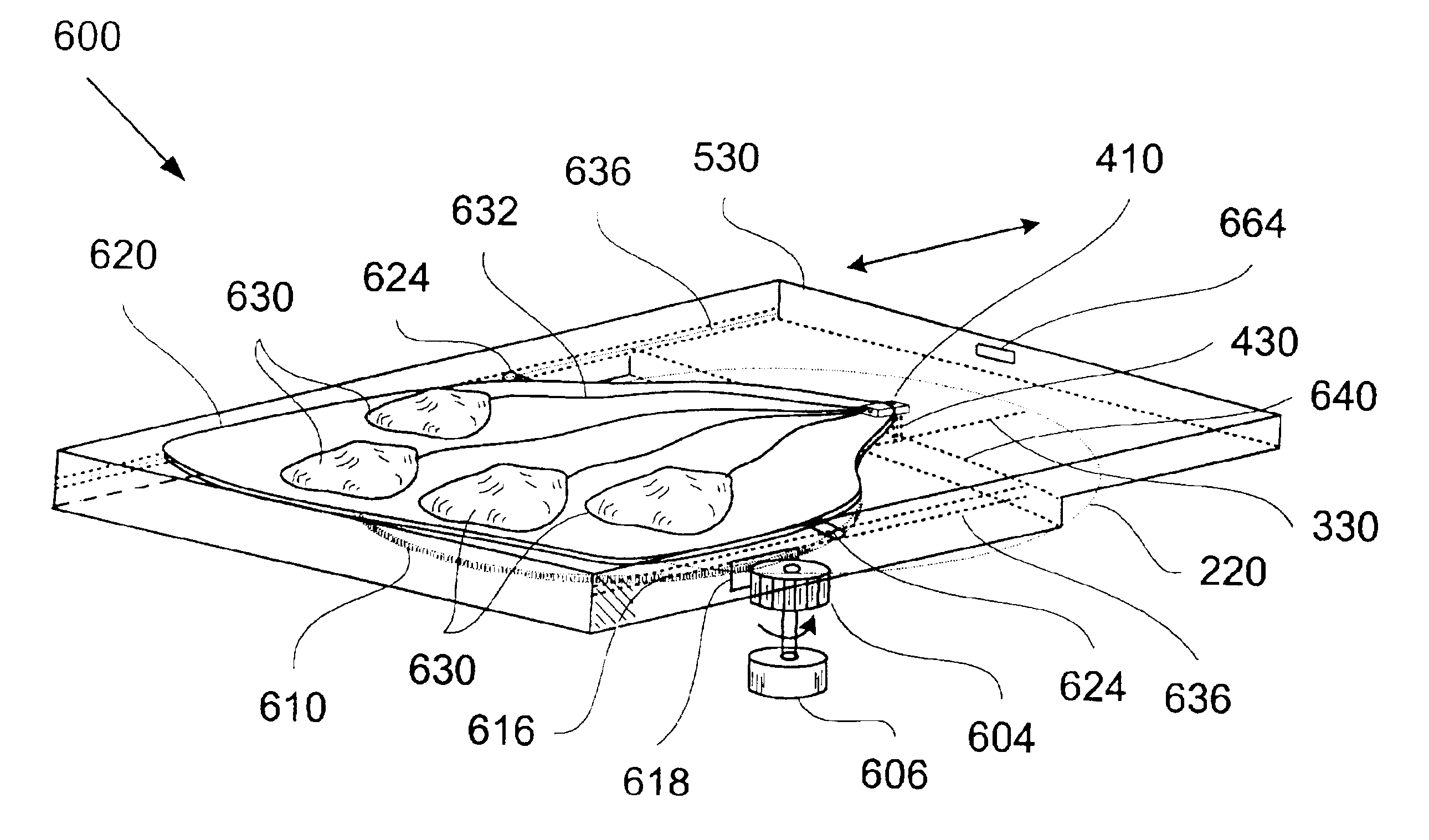
[0049]Reference will now be made in detail to a specific embodiment of the invention. An example of this embodiment is illustrated in the accompanying drawings. While the invention will be described in conjunction with this specific embodiment, it will be understood that it is not intended to limit the invention to one embodiment. On the contrary, it is intended to cover alternatives, modifications, and equivalents as may be included within the spirit and scope of the invention as defined by the appended claims. In the following description, numerous specific details are set forth in order to provide a thorough understanding of the present invention. The present invention may be practiced without some or all of these specific details. In other instances, well known process operations have not been described in detail in order not to unnecessarily obscure the present invention.

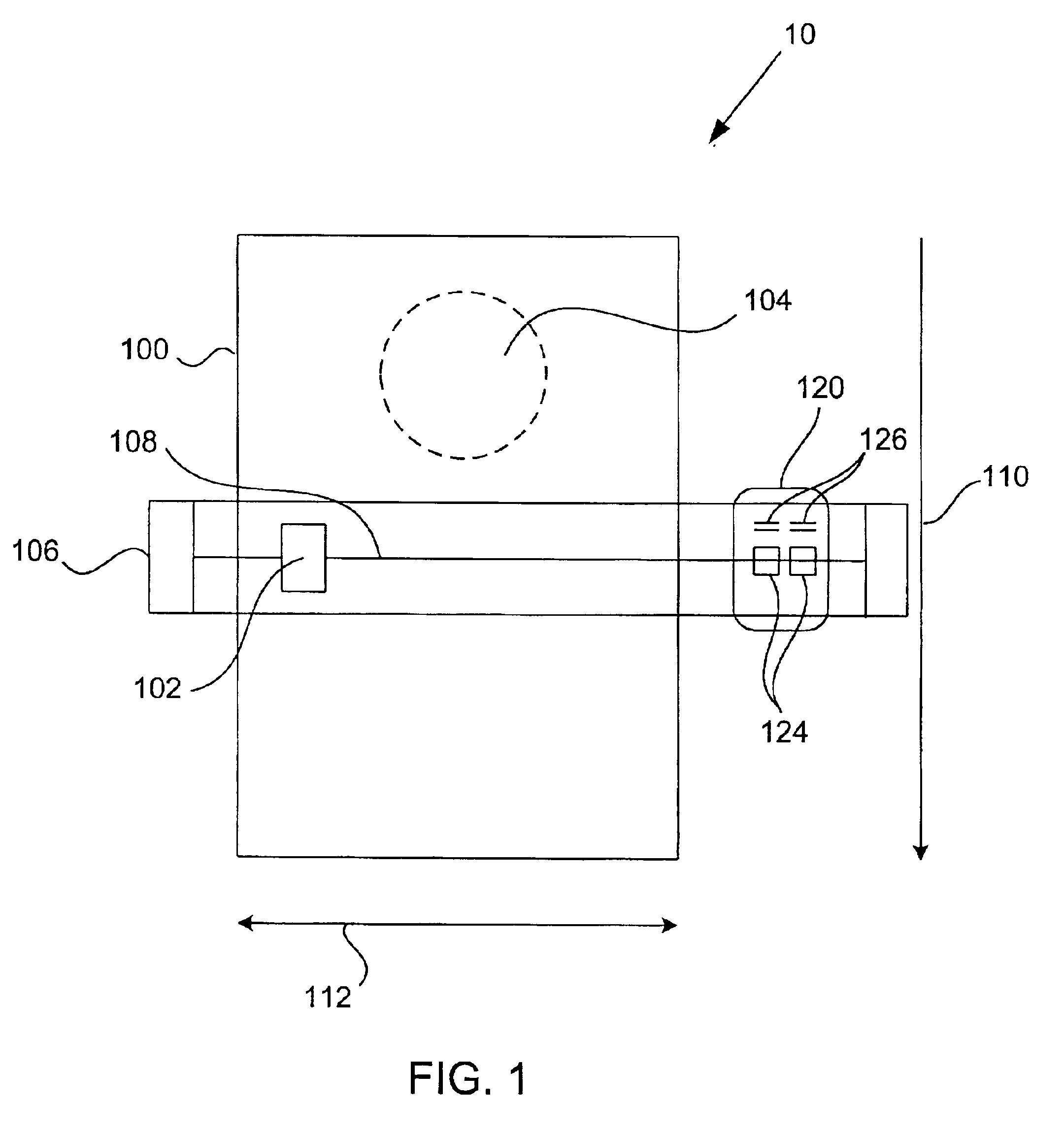
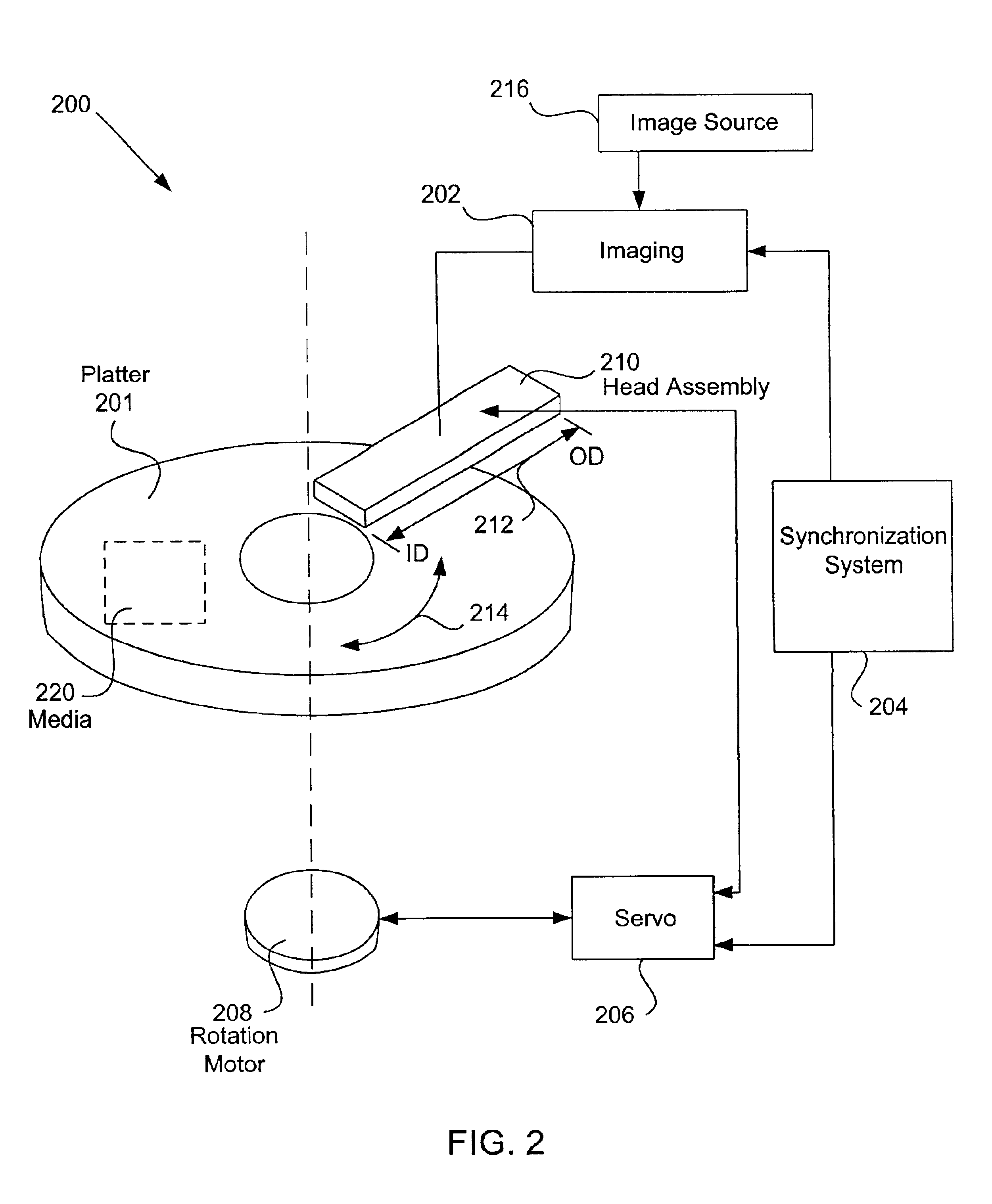
[0050]The present invention relates to circular recording media, such as an optical disc, such as a recordab...


PUM


Abstract

Disclosed are embodiments of an ink cartridge that includes therein a print head for dispensing ink onto a media, a movement mechanism for enabling movement of the print head, and/or an ink service station. In one embodiment, the cartridge is designed to be inserted into a receptacle so that the cartridge and receptacle form a radial printing system. The receptacle may also include a motion actuator for engaging with the movement mechanism of the cartridge to thereby move the print head of the cartridge. The movement mechanism of the cartridge works in conjunction with the actuator of the receptacle to thereby move the print head with respect to the cartridge, e.g., moving into and out of the cartridge, and with respect to a rotating media to enable ink to be dispensed by the print head along a radius of a rotating circular media. In a specific implementation, the cartridge remains fixed with respect to the media. In an example application, the radial print system may be used to print a label on the top surface of a recordable circular media, such as a recordable compact disc (CD-R).

Description

CROSS REFERENCE TO RELATED APPLICATIONS[0001]This application is a continuation-in-part of U.S. patent application Ser. No. 09 / 872,345, filed Jun. 1, 2001, now abandoned, which claims the benefit of U.S. Provisional Patent Application No. 60 / 208,759, filed Jun. 2, 2000. This application is also related to U.S. Pat. No. 6,264,295, issued Jul. 24, 2001. These applications and patent are incorporated herein by reference in their entirety for all purposes.BACKGROUND OF THE INVENTION[0002]The present invention relates to printing systems and methods for printing with the same. More particularly, the present invention relates to printing systems with cartridges that are configured to radially print onto a media that rotates in relation to a printing assembly.[0003]Conventional printing systems typically utilize rectangular based bitmaps. In general, a conventional printing system prints onto a standard size rectangular-shaped media along a horizontal axis, for example, and the media is mo...

Claims


Application Information

Patent Timeline
Patent Type & Authority Patents(United States)
IPC IPC(8): B41J3/407
CPCB41J3/4071
Inventor JONES, RANDY Q.UNTER, JAN E.BRADSHAW, GEORGE L.
Owner ELESYS
Why Eureka
Try Eureka