Power mower with pump lock-out system

a technology of power mower and lockout system, which is applied in the direction of mechanical equipment, non-deflectable wheel steering, transportation and packaging, etc., can solve the problems of operator's feet being left unprotected, potentially dangerous flying debris, and mowers controlled by walking operators, so as to save valuable space, less susceptible to impacting the ground, and easy operation of the mower

Inactive Publication Date: 2005-07-05
WRIGHT MFG
View PDF62 Cites 77 Cited by
  • Summary
  • Abstract
  • Description
  • Claims
  • Application Information

AI Technical Summary

Benefits of technology

This patent describes a mower for use by a standing occupant that has a platform to support the occupant. The platform is located between the first and second rear drive wheels, which reduces the risk of impacting the ground when the mower goes over bumps. The mower also has a unique handle bar and control configuration that allows the occupant to easily operate it in forward and reverse without losing balance. The front and side occupant thigh rests to help maintain hydraulic fluid temperature. A pump control lockout system prevents accidental movement of the mower, and a wheelie bar member reduces the possibility of extreme backward tipping of the mower when going up hills.

Problems solved by technology

The technical problem addressed in this patent is to create a power lawn mower that can be operated by a standing occupant with a platform that is positioned between the rear drive wheels. This positioning of the platform reduces the likelihood of tipping or rolling, increases maneuverability in tight spaces, reduces the length of the mower, and the likelihood of the operator's feet contacting the ground, and improves the overall productivity of the mower. The invention also includes a zero radius mower with a selectively deployable riding platform that can be used as a walk-behind mower or a seated occupant platform.

Method used


Image

  • Power mower with pump lock-out system
  • Power mower with pump lock-out system
  • Power mower with pump lock-out system

Examples


Embodiment Construction

[0049]Referring now more particularly to the accompanying drawings in which like reference numerals indicate like is parts throughout the several views.

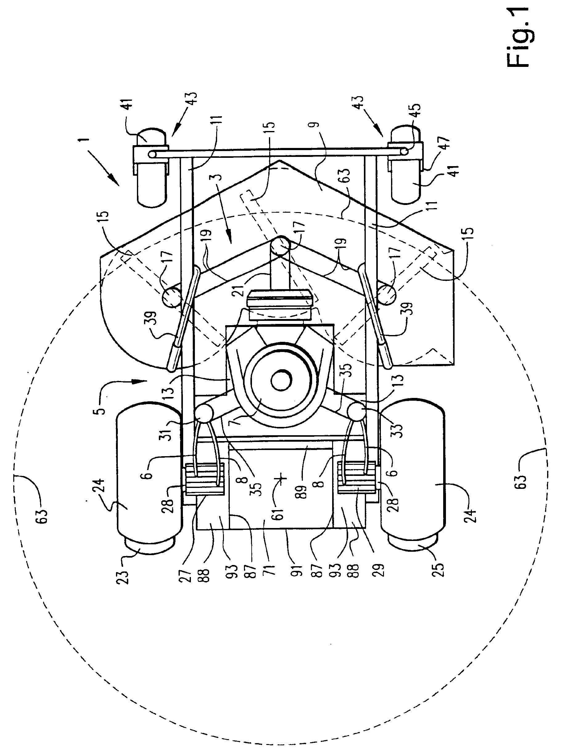
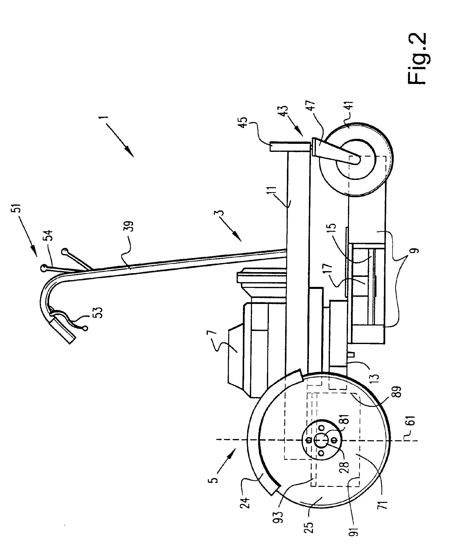
[0050]FIGS. 1 and 2 are top and side views respectively of power lawn mower 1 according to a first embodiment of this invention. Power lawn mower 1 includes cutter assembly 3 and drive assembly 5.

[0051]Cutter assembly 3 includes engine 7 and cutter or mower deck 9. Mower deck 9 is mounted on and below frame 11 in front of engine 7 and engine deck 13. Mower deck 9 is positioned close to the ground below engine deck 13, and engine 7 in certain embodiments of this invention. Decks 9 and 13 may be considered part of the frame by those of skill in the art. In the first embodiment as shown in FIG. 2, mower deck 9 is mounted on and connected to both engine deck 13 and frame 11. Frame 11 includes a pair of substantially parallel frame members which extend longitudinally along mower 1. Mower deck 9 (or alternatively the mower wheels) is verti...


PUM


Abstract

A zero turning radius power lawn mower for operation by a standing occupant includes first and second independently driven and controlled rear drive wheels mounted on separate drive axles. A riding platform for supporting the standing occupant or operator is located between the first and second rear drive wheels. The rear drive wheels are independently driveable in both the forward and reverse directions at variable speeds so as to allow for substantially zero radius turning of the mower about a central turning point. The riding platform is positioned near this turning point or axis so that the standing occupant remains substantially unaffected by centrifugal force created during approximate zero radius is turning of the mower thereby allowing the mower to take such turns at higher speeds. The low center of gravity created by the position of the riding platform for the standing operator also results in the mower having improved traction and being less likely to pop “wheelies” upon acceleration.

Description


Claims


Application Information

Patent Timeline
Owner WRIGHT MFG
Why Eureka
Try Eureka