Frame-based occupant weight estimation load cell with ball-actuated force sensor

a technology of occupant weight estimation and load cell, which is applied in the field of load cell, can solve the problems of inaccurate occupant weight estimation, bending or cross-axis sensitive strain gauge elements,

Inactive Publication Date: 2005-07-05
DELPHI TECH INC
View PDF20 Cites 9 Cited by
  • Summary
  • Abstract
  • Description
  • Claims
  • Application Information

AI Technical Summary

Benefits of technology

[0005]The present invention is directed to an improved seat frame-based occupant weight estimation load cell that transfers the seat force to a floor bracket through a spherical ball and a ball actuator. The ball is in contact with the force sensor and has minimal contact area with either the ball actuator or the force sensor so that the transfer of forces not functionally related to occupant weight is minimized. In the preferred embodiment, a ball actuator is coupled to the seat frame, and a sensor bracket aligns the ball actuator with respect to the sensor. The sensor bracket is preferably domed to securely anchor the seat to the floor bracket via the ball actuator in the event of an inverse overload. A spring disposed between the ball actuator and the dome of the sensor bracket biases the ball against the sensor to preload the sensor for enabling off-loading detection.

Problems solved by technology

One of the problems encountered with this approach is that strain gauge elements also tend to be sensitive to bending or cross-axis forces that are not functionally related to occupant weight.
In any event, the presence of such twisting or cross-axis forces tends to corrupt the z-axis force measurement, leading to inaccurate occupant weight estimation.

Method used


Image

  • Frame-based occupant weight estimation load cell with ball-actuated force sensor
  • Frame-based occupant weight estimation load cell with ball-actuated force sensor
  • Frame-based occupant weight estimation load cell with ball-actuated force sensor

Examples


Embodiment Construction

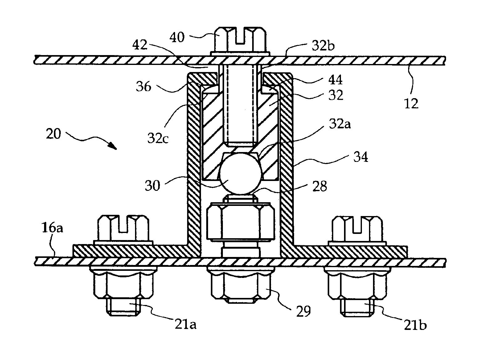
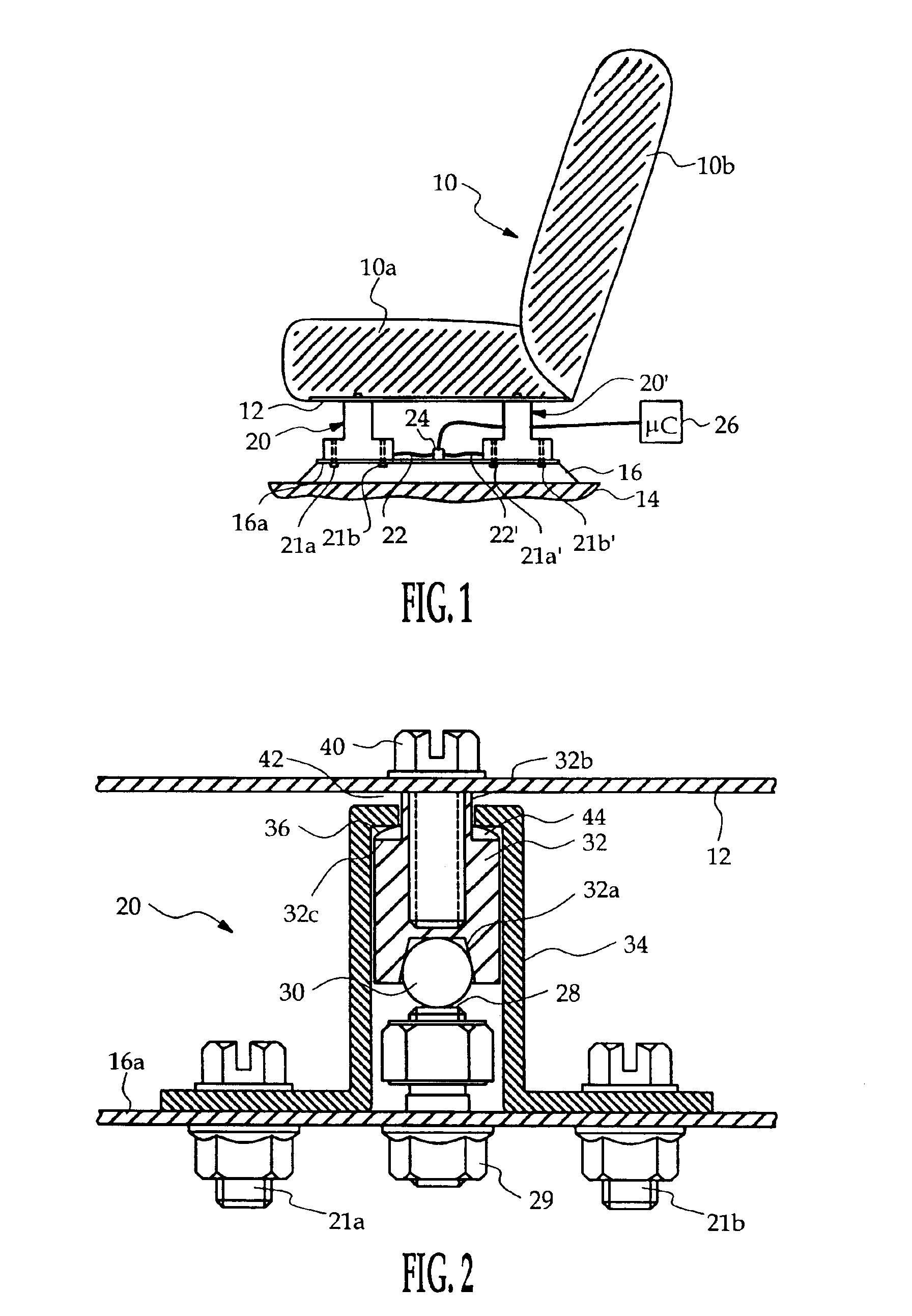
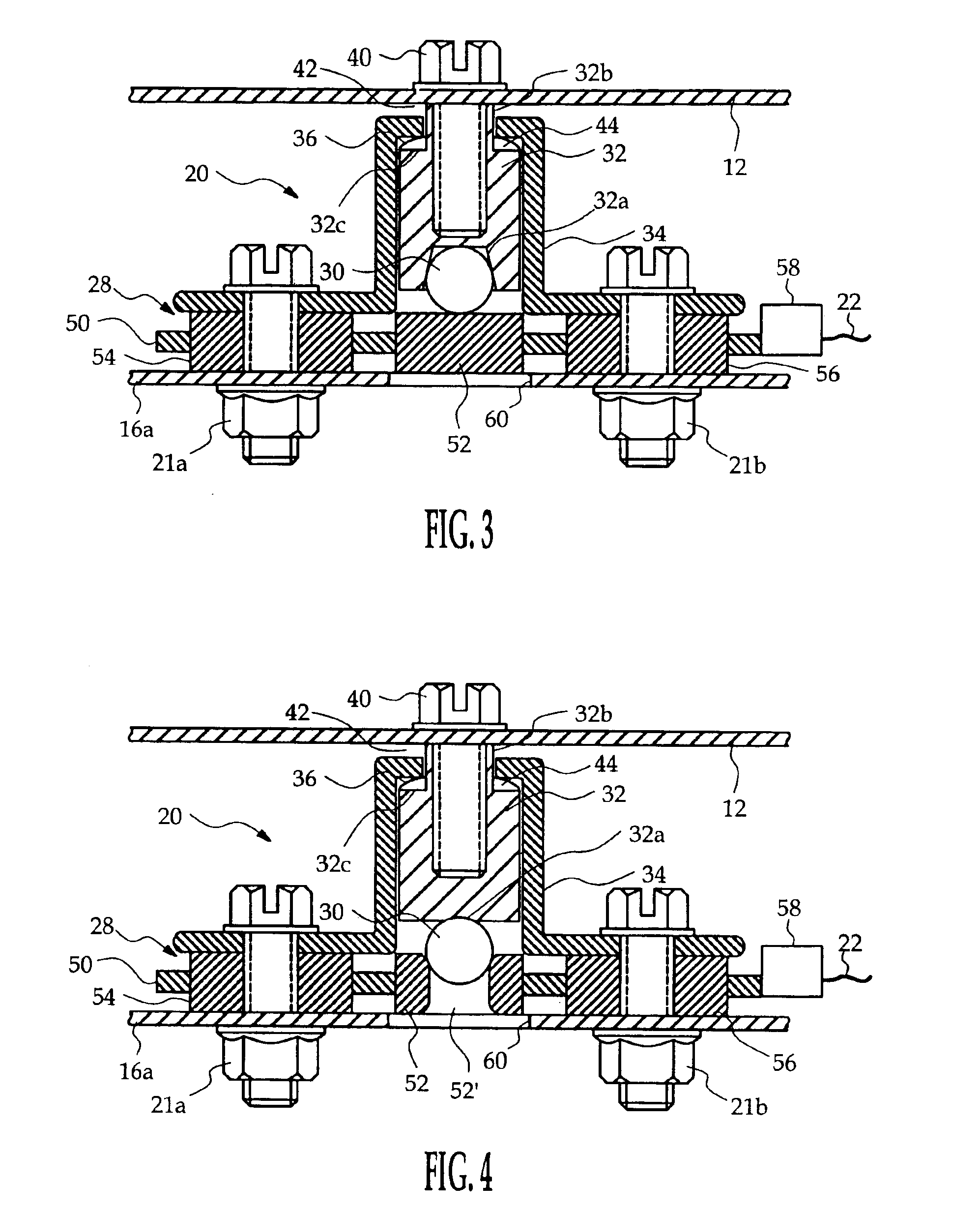
[0011]Referring to the drawings, and particularly to FIG. 1, the reference numeral 10 generally designates a vehicle seat, including seat and backrest cushions 10a, 10b supported on a metal frame 12. The seat 10 is secured to the vehicle floor 14 by a pair of laterally spaced floor brackets 16, only one of which is shown in FIG. 1. The floor bracket 16 is bolted to floor 14, and a set of load cells 20, 20′ are interposed between the seat frame 12 and the floor bracket 16 for supporting the seat 10 and estimating the weight of a seat occupant. In the illustrated embodiment, the floor bracket 16 includes an integral flange 16a, and the load cells 20, 20′ are secured to the floor bracket 16 by a set of bolts 21a, 21b; 21a′, 21b′ that seat against flange 16a. The load cells 20, 20′ produce electrical outputs on lines 22, 22′ indicative of the forces transmitted therethrough; the lines 22 and 22′ are coupled to a connector 24, which in turn is electrically coupled to a microcontroller (u...


PUM

PropertyMeasurementUnit
weightaaaaaaaaaa
pressureaaaaaaaaaa
forcesaaaaaaaaaa

Abstract

A seat frame-based occupant weight estimation load cell transfers the seat force to a floor bracket through a spherical ball and a ball actuator. The ball is in contact with the force sensor and has minimal contact area with either the ball actuator or the force sensor so that the transfer of forces not functionally related to occupant weight is minimized. The ball actuator is coupled to the seat frame, and a sensor bracket aligns the ball actuator with respect to the sensor. The sensor bracket is domed to securely anchor the seat to the floor bracket in the event of an inverse overload. A spring disposed between the ball actuator and the dome of the sensor bracket biases the ball against the force sensor to preload the force sensor for enabling off-loading detection.

Description

TECHNICAL FIELD[0001]This invention is directed to apparatus for detecting the weight of an occupant of a motor vehicle seat for purposes of determining whether and how forcefully to deploy supplemental restraints, and more particularly to a load cell for measuring forces applied to a frame of the vehicle seat.BACKGROUND OF THE INVENTION[0002]Vehicle occupant detection systems are useful in connection with air bags and other pyrotechnically deployed restraints as a means of judging whether, and how forcefully, to deploy the restraint. One fundamental parameter in this regard is the weight of the occupant, as weight may be used as a criterion to distinguish between an adult and an infant or small child.[0003]Most prior weight estimation techniques involve installing a pressure sensitive element such as a variable resistance pad or a fluid filled bladder in or under a vehicle seat cushion, and utilizing the pressure measurement as an indication of occupant weight. See, for example, th...

Claims


Application Information

Patent Timeline
Patent Type & Authority Patents(United States)
IPC IPC(8): G01G19/414G01G19/40B60N2/00B60N2/015
CPCB60N2/002B60N2/015G01G19/4142
Inventor FORTUNE, DUANE D.MURPHY, MORGAN D.
Owner DELPHI TECH INC
Why Eureka
Try Eureka