Golf ball with improved flight performance

a technology of aerodynamic characteristics and golf balls, applied in the field of golf balls having improved aerodynamic characteristics, can solve the problems of asymmetric flight performance, difficult to identify incremental performance improvement using these methods, and difference in pressure, and achieve the effect of high percentage of dimple coverage and better dimple packing

Inactive Publication Date: 2005-07-05
ACUSHNET CO
View PDF48 Cites 39 Cited by
  • Summary
  • Abstract
  • Description
  • Claims
  • Application Information

AI Technical Summary

Benefits of technology

[0023]The present invention is also directed to a golf ball dimple pattern that provides a surprisingly better dimple packing than any previous pattern so that a greater percentage of the surface of the golf ball is covered by dimples. The prior art golf balls have dimple patterns that leave many large sp

Problems solved by technology

The flight of a golf ball is determined by many factors, however, the majority of the properties that determine flight are outside of the control of a golfer.
Flight consistency is a significant problem for manufacturers because the many of golf ball dimple patterns and/or dimple shapes that yield increased flight distance also result in asymmetric flight performance.
Furthermore, it is difficult to identify incremental performance improvements using these methods due to the statistical noise generated by environmental conditions, which necessitates large sample sizes for sufficient confidence intervals.
It results from a difference in pressure that is created by a distortion in the air flow that results from the back spin

Method used


Image

  • Golf ball with improved flight performance
  • Golf ball with improved flight performance
  • Golf ball with improved flight performance

Examples


third embodiment

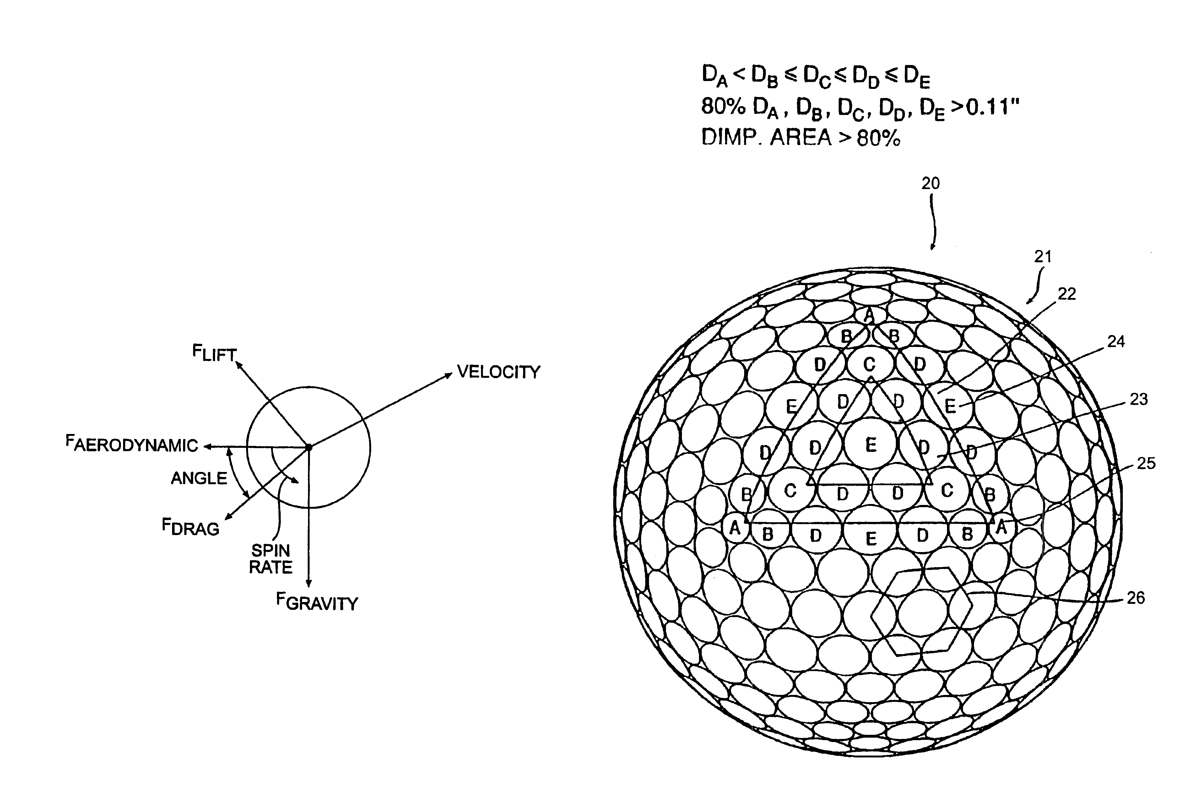
[0116]One embodiment of the present invention contemplates dimple coverage of greater than about 80 percent. For example, the percentages of surface area covered by dimples in the embodiments shown in FIGS. 7-8 and 9-12 are about 85.7 percent and 82 percent, respectively whereas the ball shown in FIG. 5 has less than 80 percent of its surface covered by dimples. The percentage of surface area covered by dimples in the third embodiment shown in FIGS. 13-14 is also about 82 percent, whereas prior art octahedral balls have less than 77 percent of their surface covered by dimples, and most have less than 60 percent. Thus, there is a significant increase in surface area contemplated for the golf balls of the present invention as compared to prior art golf balls.

Parting Line

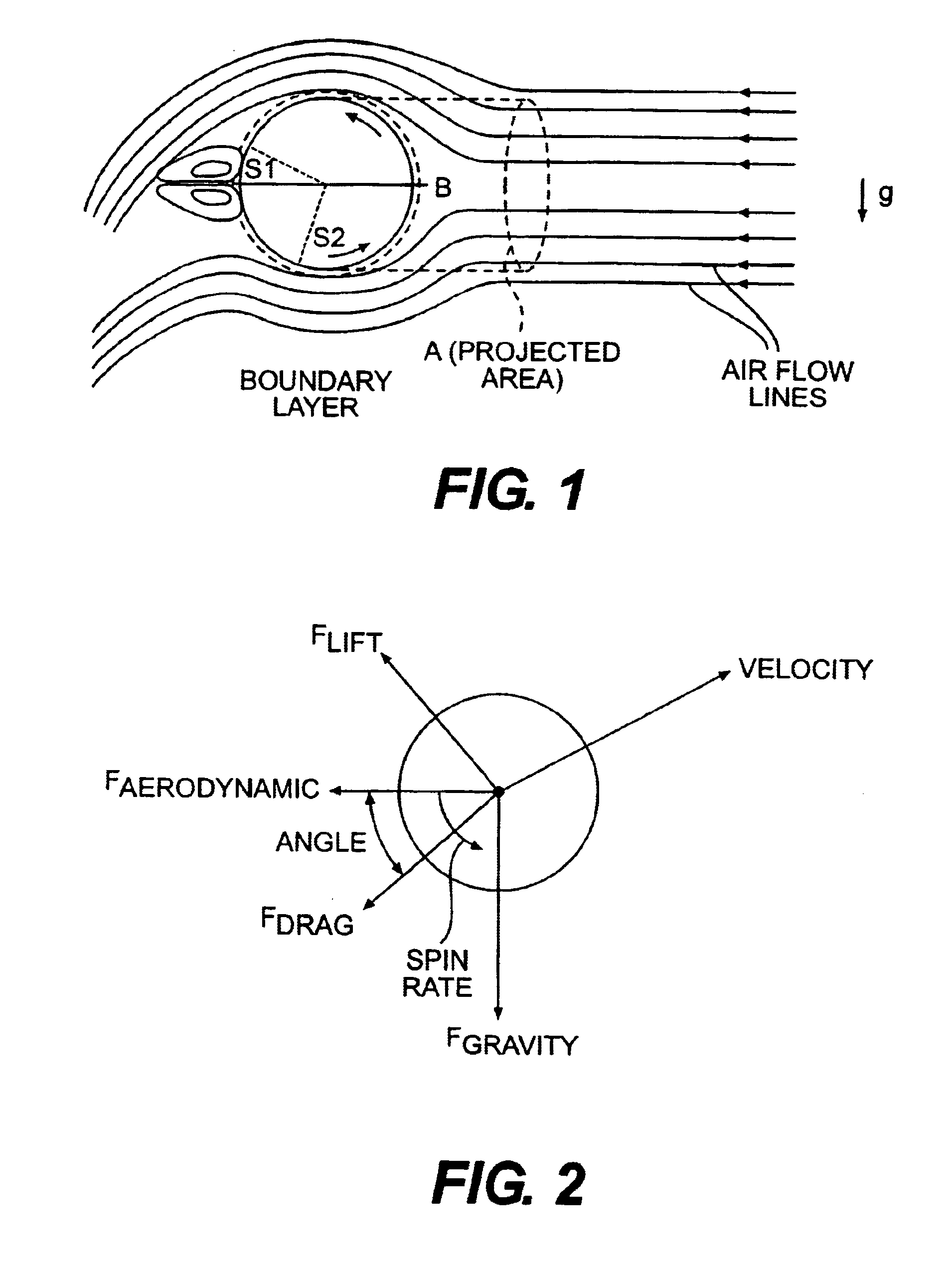
[0117]A parting line, or annular region, about the equator of a golf ball has been found to separate the flow profile of the air into two distinct halves while the golf ball is in flight and reduce the aerodynamic forc...

first embodiment

[0120]In another embodiment, there are more than two parting lines that do not intersect any dimples. For example, the octahedral golf ball shown in FIGS. 13-14 contains three parting lines 38 that do not intersect any dimples. This decreases the percentage of the outer surface as compared to the first embodiment, but increases the symmetry of the dimple pattern.

[0121]In another embodiment, the golf balls according to the present invention may have the dimples arranged so that there are less than four parting lines that do not intersect any dimples.

Dimple Count

[0122]In one embodiment, the golf balls according to the present invention have about 300 to about 500 total dimples. In another embodiment, the dimple patterns are icosahedron patterns with about 350 to about 450 total dimples. For example, the golf ball of FIGS. 7-8 have 362 dimples. In the golf ball shown in FIGS. 9-12, there are 392 dimples and in the golf ball shown in FIGS. 13-14, there are 440 dimples.

Dimple Diameter

[01...


PUM


Abstract

A golf ball with aerodynamic coefficient magnitude and aerodynamic force angle, resulting in improved flight performance, such as increased carry and flight consistency regardless of ball orientation. In particular, the present invention is directed to a golf ball having increased flight distance as defined by a set of aerodynamic requirements, at particular spin ratios and Reynolds Numbers. The invention is also directed toward golf balls with dimple diameters of greater than 6.5 percent of the ball diameter and dimples with a profile defined by a catenary curve.

Description

CROSS-REFERENCE TO RELATED APPLICATIONS[0001]This application is a continuation of U.S. patent application Ser. No. 10 / 096,852, filed Mar. 14, 2002 now U.S. Pat. No. 6,729,976, which is a continuation-in-part of U.S. patent application Ser. No. 09 / 989,191, filed Nov. 21, 2001 now U.S. Pat. No. 6,796,912, and also a continuation-in-part of U.S. patent application Ser. No. 09 / 404,164, filed Sep. 27, 1999 now U.S. Pat. No. 6,358,161, now allowed, which is a divisional of U.S. patent application Ser. No. 08 / 922,633, filed Sep. 3, 1997, now U.S. Pat. No. 5,957,786. The entire disclosures of the related applications are incorporated by reference herein.FIELD OF THE INVENTION[0002]The present invention relates to golf balls having improved aerodynamic characteristics that yield improved flight performance and longer ball flight. The improved aerodynamic characteristics are obtained through the use of specific dimple arrangements and dimple profiles. The aerodynamic improvements are applica...

Claims


Application Information

Patent Timeline
IPC IPC(8): A63B37/00
CPCA63B37/0004A63B37/0012A63B37/0006A63B37/002A63B37/0021A63B37/008A63B37/0083A63B37/0089A63B37/009A63B37/0096A63B37/0026A63B37/00065A63B37/0077A63B37/00215
Inventor BISSONNETTE, LAURENT C.DALTON, JEFFREY L.AOYAMA, STEVEN
Owner ACUSHNET CO
Why Eureka
Try Eureka