Telecommunications patch panel with angled connector modules

a patch panel and connector technology, applied in the field of cross-connect patch panels, can solve problems such as damage and/or loss of performance, adversely affecting performance,

Inactive Publication Date: 2005-07-12
COMMSCOPE TECH LLC
View PDF30 Cites 104 Cited by
  • Summary
  • Abstract
  • Description
  • Claims
  • Application Information

AI Technical Summary

Problems solved by technology

One area where damage and / or loss of performance may occur with copper based, twisted pair cables is when excessive bending of the cable occurs.
Falling below minimum bend radii of the cables can adversely affect performance with the transmission of signals through the copper wire patch cords.

Method used


Image

  • Telecommunications patch panel with angled connector modules
  • Telecommunications patch panel with angled connector modules
  • Telecommunications patch panel with angled connector modules

Examples


Embodiment Construction

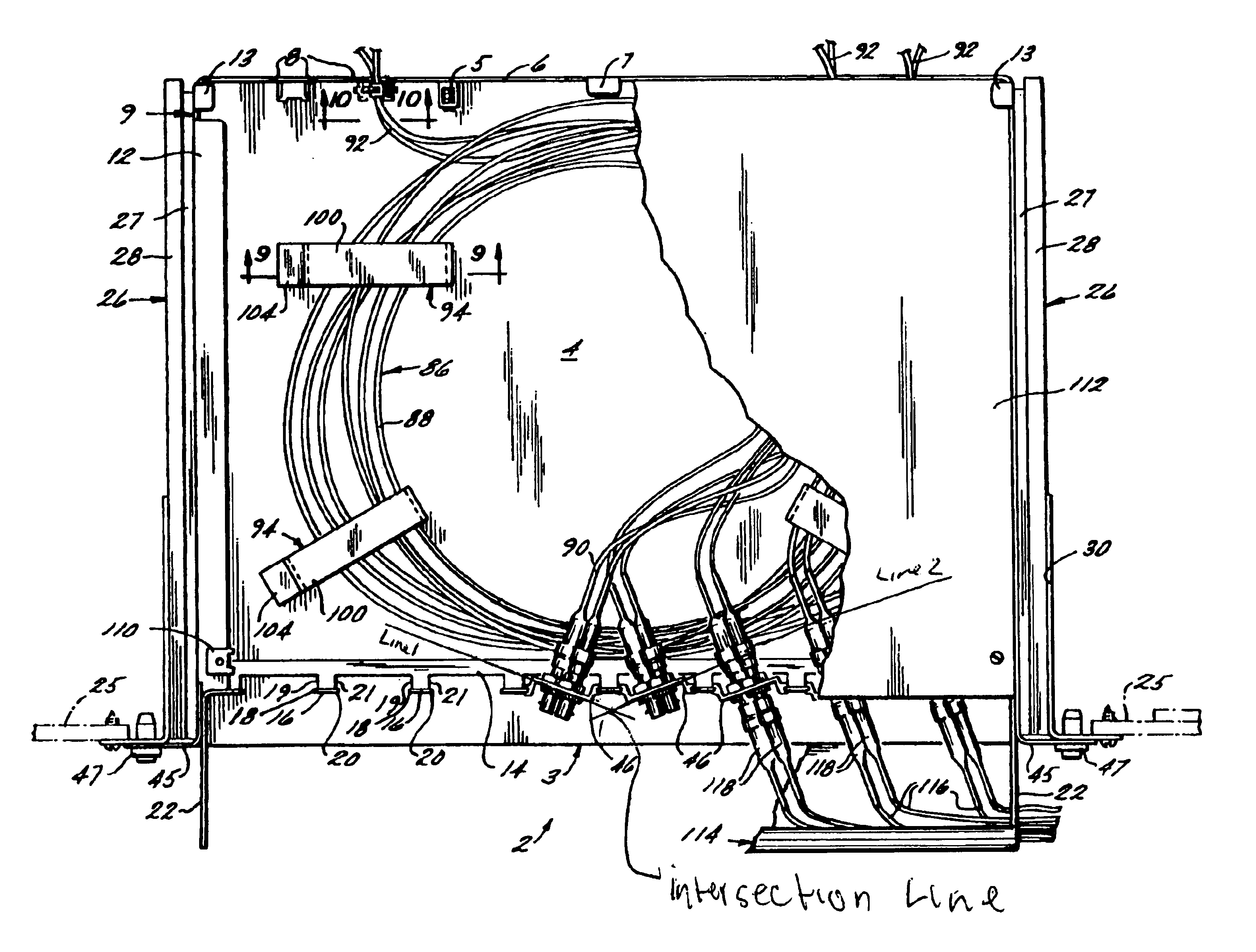
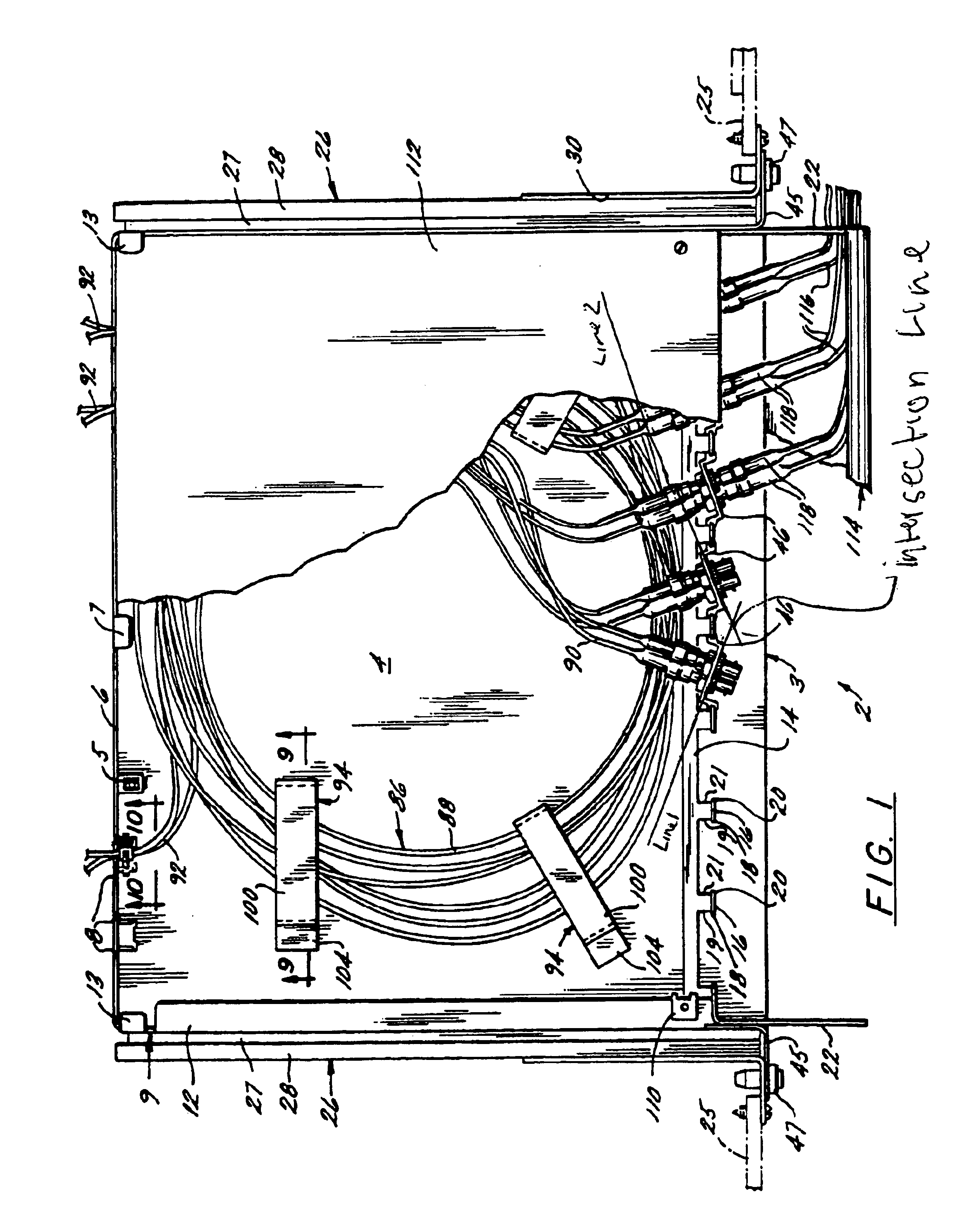
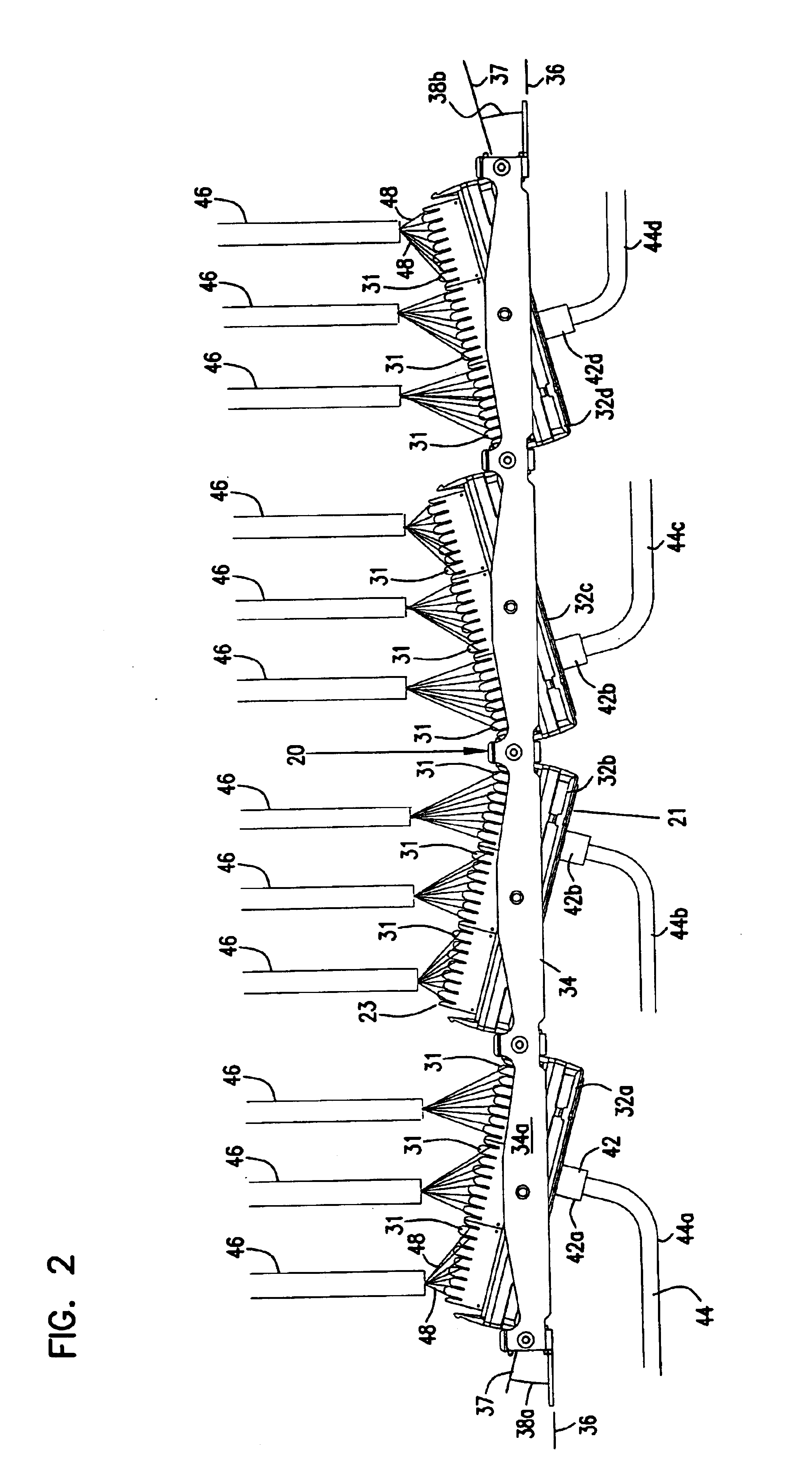
[0025]Referring now to FIGS. 1 and 2, an embodiment of a patch panel 20 is shown for use in connecting telecommunications equipment. Patch panel 20 is especially useful to cross-connect equipment through one or more of patch panels 20 or other panels. Patch panel 20 mounts to a rack 22 of conventional construction, such as with fasteners 26 passing through holes 28 of patch panel 20 for receipt in holes 24 of rack 22. Patch panel 20 includes a plurality of connector jacks 30, such as RJ45 connector jacks, on a front side 21. Patch panel 20 further includes a plurality of connection locations 31, such as wire termination or connection blocks 31 mounted on an opposite rear side 23. Preferably, termination blocks 31 include 110 type insulation displacement connectors. Termination blocks 31 allow for connection of signal transmission cables 46, each containing a plurality of conductive wires 48. Connector jacks 30 allow for connection of signal transmission patch cables or cords 44 incl...


PUM


Abstract

A telecommunications patch panel is provided having a plurality of connector modules rotatably mounted to a frame member. Each connector module has a front face and an opposite facing rear face, and each front face includes a plurality of connector jacks. Each rear face includes a plurality of wire termination blocks. The wire termination blocks are electrically connected to the connector jacks. Each connector module is rotatable about a rotation axis relative to the frame member. A lock selectively locks each connector module to the frame member as desired. The connector jacks and the connector modules are arranged in linear arrays perpendicular to the axis of rotation.

Description

[0001]“This application is a continuation of application Ser. No. 09 / 092,545, filed Jun. 5, 1998 now U.S. Pat. No. 6,537,106, which application(s) are incorporated herein by reference.”FIELD OF THE INVENTION[0002]The present invention relates to a telecommunications connecting panel and, more particularly, to a cross-connect patch panel including a frame with jacks on one side and wire termination locations on an opposite side.BACKGROUND OF THE INVENTION[0003]Local area networks and telecommunications connections often use patch panels, especially at the customer's premises to enable cross-connection between telecommunications equipment. Patch panels typically include front and rear connection locations. The rear connections are typically a more permanent type of connection, such as insulation displacement connectors to connect to copper based, twisted pair telecommunications cable. The front connections of the patch panel may include any of a variety of jacks for receipt of a plug ...

Claims


Application Information

Patent Timeline
Patent Type & Authority Patents(United States)
IPC IPC(8): H01R13/518H01R13/516H04Q1/02H04Q1/14H01R13/73H01R25/00
CPCH01R13/518H01R13/748H01R35/04H04Q1/09H04Q1/13H01R2201/04H01R2201/16H01R24/64H04Q2201/10H04Q2201/12Y10S439/954H04Q1/148H01R13/74H01R2107/00
Inventor FOLLINGSTAD, MICHAEL JAY
Owner COMMSCOPE TECH LLC
Why Eureka
Try Eureka