Dual-layer heat dissipating structure

a heat dissipating structure and dual-layer technology, applied in the direction of electrical apparatus construction details, indirect heat exchangers, lighting and heating apparatus, etc., can solve the problem of large heat generation, and achieve the effect of strengthening the join

Inactive Publication Date: 2005-07-19
CPUMATE INC
View PDF12 Cites 67 Cited by
  • Summary
  • Abstract
  • Description
  • Claims
  • Application Information

AI Technical Summary

Problems solved by technology

The improved functions and operation speed of these electronic devices has consequently produced great amount of heat.

Method used


Image

  • Dual-layer heat dissipating structure
  • Dual-layer heat dissipating structure
  • Dual-layer heat dissipating structure

Examples


second embodiment

[0028]FIGS. 6 and 7 show the present invention. FIG. 6 is a cross-sectional view, while FIG. 7 is an enlarged view of area A as shown in FIG. 6. In this embodiment, the protruding rib 124 has a dovetail cross section, while the recessed channel 114 is configured to conform to the dovetail cross section.

third embodiment

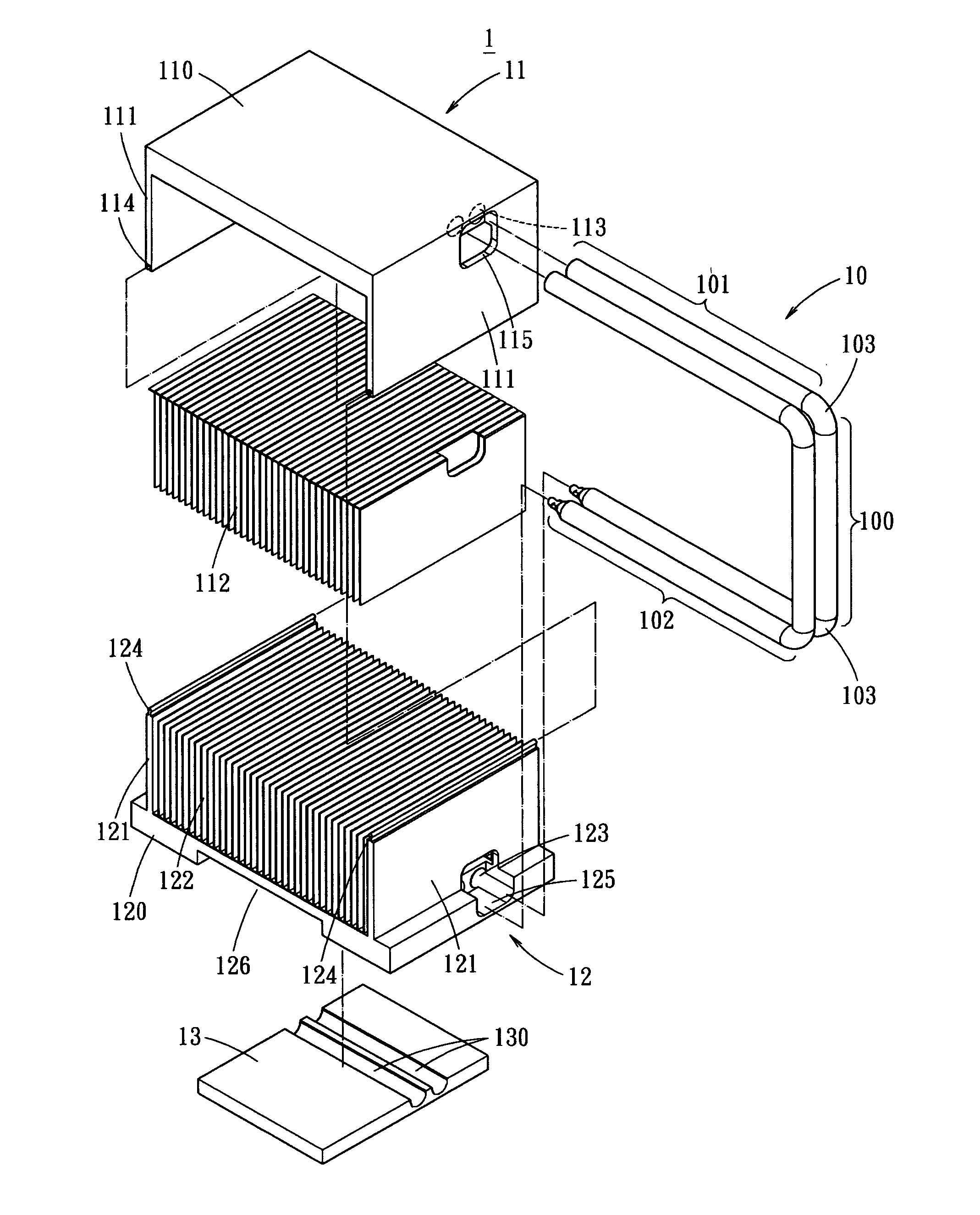
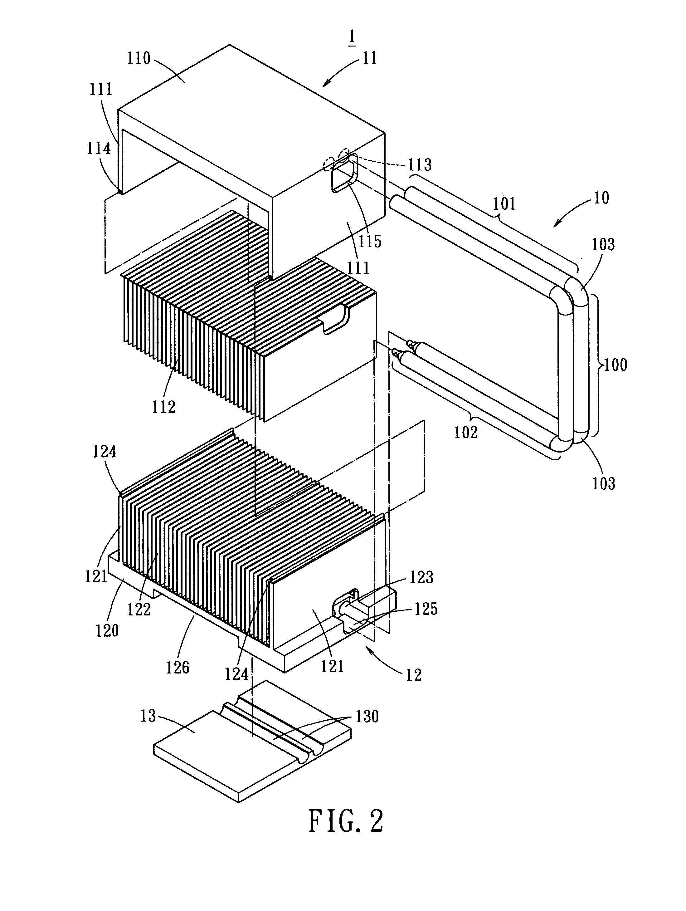
[0029]FIG. 8 shows an exploded view of the present invention. In this embodiment, the first and second heat sinks 11 and 12 are aluminum extruded heat sinks. That is, each of the fins 112 and 122 is integrally formed on the substrates 110 and 120, respectively.

[0030]As shown in FIG. 9, the above-mentioned snapping structure includes a slit 116 and a protrusion 127. The slit 116 and the protrusion 127 are formed on each two corresponding end plates 111, 121 of the heat sinks 11, 12. For example, the first heat sink 11 has the slit 116 and the protrusion 127 formed on each end plate 111, while the second heat sink 12 has the protrusion 127 and the slit 116 formed on the corresponding end plate 121, respectively. Therefore, the heat sinks 11 and 12 may be identical by molding. After the heat sinks 11 and 12 are mounted together, the engagement of the slit 116 and the protrusion 127 thereof are well performed by simply pressing the end plates 111 and 121 to deform the slit 116 and protr...


PUM


Abstract

A dual-layer heat dissipating structure includes a first heat sink, a second heat sink, and a heat pipe with a connecting portion and a curved portion, interconnecting the first and second heat sinks for thermal conduction. The first and second heat sinks each has a substrate and exterior fins protruding from two opposing ends thereof. Two substrates each includes at least one slot through out of two corresponding end plates of the same side for locating the connecting portion, and the corresponding end plates each includes an opening with respect to the slot for partially moving in the curved portion. The exterior fins of the first and second heat sinks are aligned with each other, and a snap-type connecting structures are formed on terminuses of the exterior fins. The second and first heat sinks are connected to each other by the snap-type structure, and the connection joint is reinforced by implanting soldering material.

Description

BACKGROUND OF THE INVENTION[0001]The present invention relates to a dual-layer heat dissipating structure and, more particularly, to a dual-layer heat dissipating structure which employs a heat pipe between two heat sinks, while connection between two heat sinks is reinforced.[0002]The advancement of computer technology has introduced various types of high-precision electronic devices. The improved functions and operation speed of these electronic devices has consequently produced great amount of heat. How to effectively dissipate the heat generated by the electronic devices, and how to maintain the operation temperature of the electronic devices has become an important topic in industry.[0003]FIG. 1 shows a conventional heat dissipating structure 1a. The heat dissipating structure 1a uses a heat pipe 10a serially connecting two heat sinks 11a and 12a. When the lower heat sink 12a is in contact with the heat generating electronic device, a part of the heat is conducted towards the u...

Claims


Application Information

Patent Timeline
Patent Type & Authority Patents(United States)
IPC IPC(8): F28D15/02H01L21/48H01L21/02H01L23/427H01L23/34
CPCF28D15/0275H01L21/4882H01L23/427H01L2924/0002H01L2924/00F28F2275/085
Inventor LIN, KUO-LENTSUI, HUI-MIN
Owner CPUMATE INC
Why Eureka
Try Eureka