High-temperature optical rotary and linear position sensor

a technology of optical rotary and linear position sensor, which is applied in the direction of converting sensor output optically, instruments, measurement devices, etc., can solve the problems of limiting accuracy, affecting the accuracy of measurement, and often complicated tasks

Inactive Publication Date: 2005-07-19
HONEYWELL INT INC
View PDF17 Cites 4 Cited by
  • Summary
  • Abstract
  • Description
  • Claims
  • Application Information

AI Technical Summary

Problems solved by technology

This is a task often complicated by high temperatures, magnetic interference and vibration.
In these encoders the angular information generally is lost if this reference angle becomes corrupted.
This may occur for a number of reasons such as power interruption or magnetic interference.
Also, some of these encoders achieve additional sensitivity by means of gear trains which are subject to hysteresis which limit accuracy and make angular determination indirect.
Another problem with devices that rely on low level electrical signals to determine the distance and/or angular displacement between two parts is inability to deliver accurate reading at elevated temperature such as between 500° F. and 1000° F.
Although optical encoder rotation sensors function satisfactorily for certain applications, their use in many applications is limited because of size and weight limitations.
This device has significant disadvantages in high temperature operations such as jet engines and gas turbines in that the measuring device may be dirtied.
For apparatus that rely on intensity or analog measure

Method used


Image

  • High-temperature optical rotary and linear position sensor
  • High-temperature optical rotary and linear position sensor
  • High-temperature optical rotary and linear position sensor

Examples


Embodiment Construction

[0016]The following detailed description is of the best currently contemplated modes of carrying out the invention. The description is not to be taken in a limiting sense, but is made merely for the purpose of illustrating the general principles of the invention, since the scope of the invention is best defined by the appended claims.

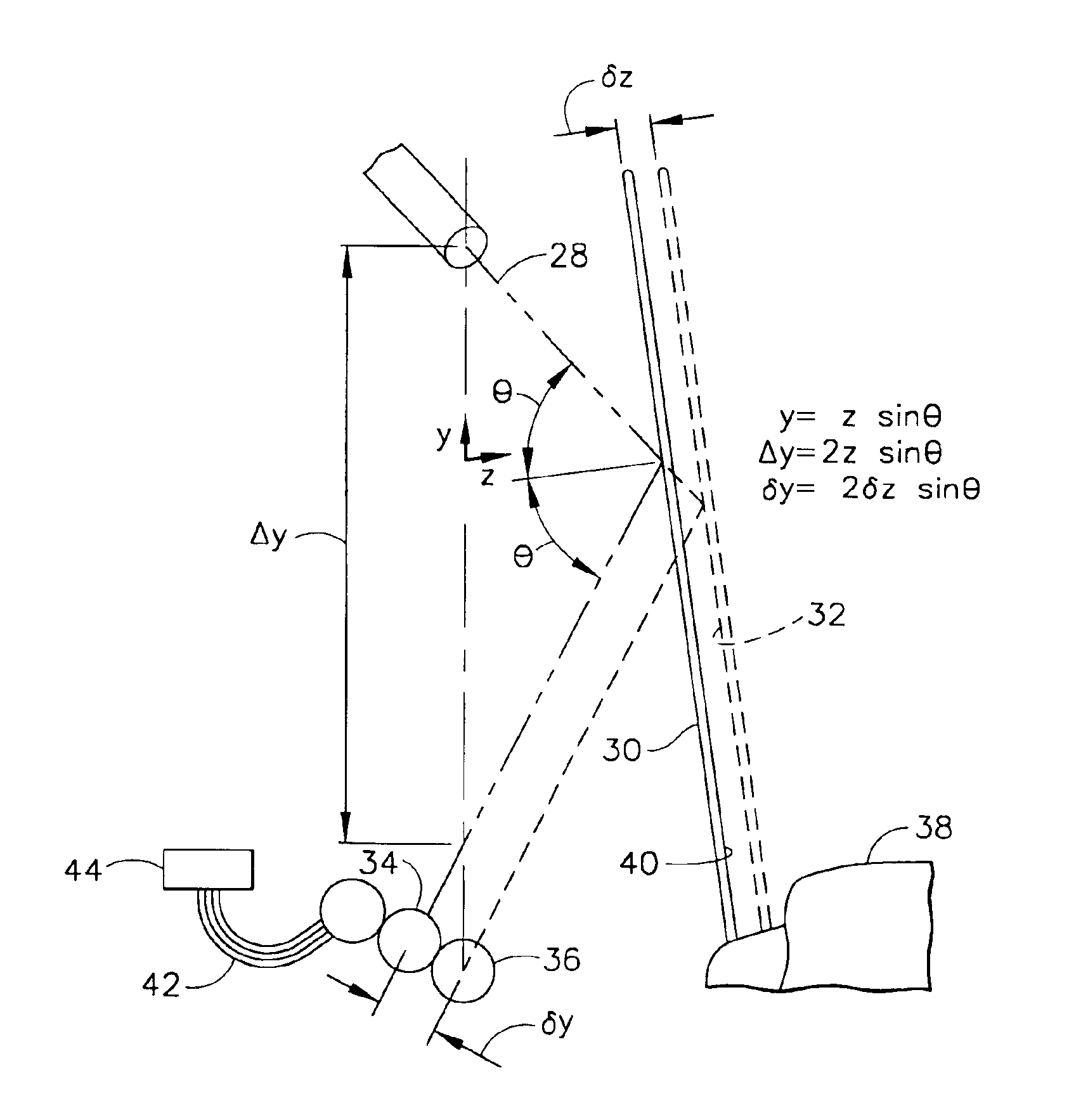
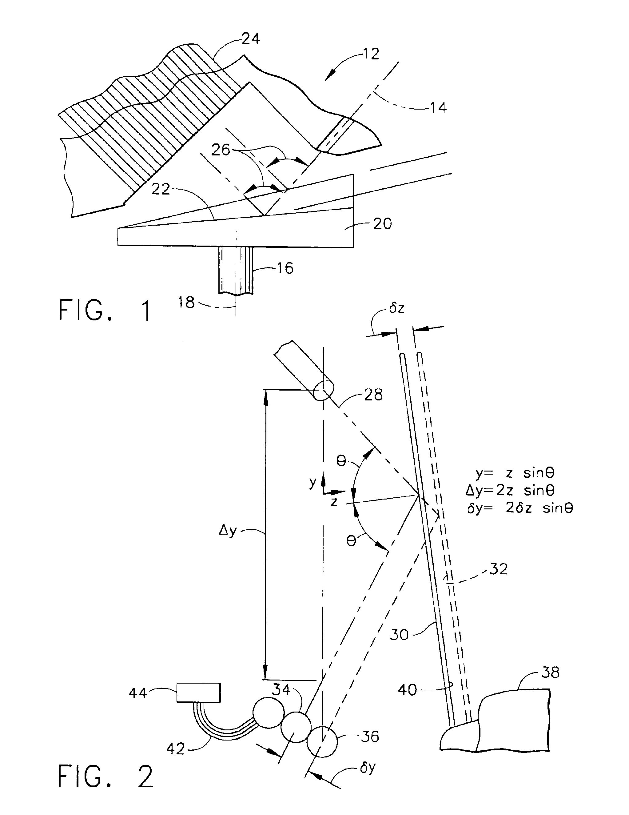
[0017]The present invention generally provides a means to measure the position, both rotary and linear, of at least one member. It is an object of the present invention to be utilized at high temperatures without any effect on the accuracy of readings. By way of example, the present invention may be particularly well suited for aerospace applications, such as jet engine bleed air valves. The present invention differs from the prior art in that it provides a rotating and linear position sensor that utilizes a multitude of light receiving members and geometry to determine the position of a second member relative to a first member. As such, optics are util...


PUM


Abstract

A device and method capable of measuring the optical rotary and linear position of items, that is reliable, accurate and capable of operating in harsh environments. The present invention utilizes optics to measure rotary and linear position. Unlike the prior art the present invention relies on the optical angle to determine position rather than an analog signal or intensity. Because of this, the present invention is capable of providing accurate results in high temperature, harsh and dirty environments. Further, the present invention reduces the need for time consuming and costly replacements at the sensing end.

Description

BACKGROUND OF THE INVENTION[0001]The present invention generally relates to devices that measure the location of a rotatable member. More particularly, the present invention provides a device and method, capable of measuring the optical rotary and linear position of items, and that is reliable, accurate, immune to EMI and capable of operating in harsh environments.[0002]Many scientific, industrial, military and aerospace applications require precise and accurate knowledge of the angular orientation of a shaft or other rotating object or the linear position of a reciprocating object. This is a task often complicated by high temperatures, magnetic interference and vibration. A variety of rotation sensors are currently available in the art for sensing or measuring relative rotation of a rotatable member. These devices generally record very small angular changes and keep track of accumulated change relative to some reference angle. In these encoders the angular information generally is ...

Claims


Application Information

Patent Timeline
IPC IPC(8): G01D5/347G01D5/26G01D5/28
CPCG01D5/28G01D5/347
Inventor MCCARTY, ROBERT S.SHIEFMAN, JOE
Owner HONEYWELL INT INC
Why Eureka
Try Eureka