Multi-layer method of accommodating code collisions from multiple surface acoustic wave identification tags

a technology of acoustic wave identification and a code collision, which is applied in the field of identification tags, can solve the problems of insufficient detection of code collisions, interference problems, and low detection efficiency, and achieve the effects of effective discrimination and isolation of signals, robust saw identification tags, and reduced code response pulses

Inactive Publication Date: 2005-07-19
RF SAW COMPONENTS INC
View PDF5 Cites 8 Cited by
  • Summary
  • Abstract
  • Description
  • Claims
  • Application Information

AI Technical Summary

Benefits of technology

[0008]The present invention thus provides a method for identifying a coded response returned by a specific SAW identification tag when such response is included within a number of other coded signals being simultaneously returned. The present invention provides a useful and beneficial solution to a perceived problem of SAW identification tags always being in the “on” state. By being able to effectively discriminate and isolate a signal from among multiple signals, relatively inexpensive and robust SAW identification tags can be effectively used where other identification methodologies have proven to be deficient.
[0009]In one embodiment, the method includes focusing an interrogation pulse to within a defined space and, thus, reducing the number of coded response pulses returned. Because fewer signals are considered, potential code collisions are reduced with a corresponding reduction in identification response time.

Problems solved by technology

Although silicon chip based RFID tag systems have a longer read range than magnetic strip or bar code systems, the tags are relatively expensive and are not widely used (except for limited applications such as toll tags and security systems), which means most such prior art RFID tags will also generally be individually read with little opportunity for one such tag to interfere with another.
Up to the present time, the current state of the art has not addressed the significant signal collision problem caused by simultaneous identification tag responses.
The problem is quite apparent when a number of SAW tags are simultaneously interrogated, which will occur frequently because SAW technology permits tags to be read at a relatively long range.
With each SAW tag responding to the interrogation signal, it is a certainty that interference problems will occur.
Because each SAW identification tag on each article will respond by transmitting its own globally unique coded response signal, it may be difficult to process the mass of signal data to accurately detect and decode each response and reliably identify each article.
This kind of code collision problem as well as other interference problems caused by so much data being transmitted at one time must be resolved before the full potential of SAW identification tag technology can be realized.

Method used


Image

  • Multi-layer method of accommodating code collisions from multiple surface acoustic wave identification tags
  • Multi-layer method of accommodating code collisions from multiple surface acoustic wave identification tags
  • Multi-layer method of accommodating code collisions from multiple surface acoustic wave identification tags

Examples


Embodiment Construction

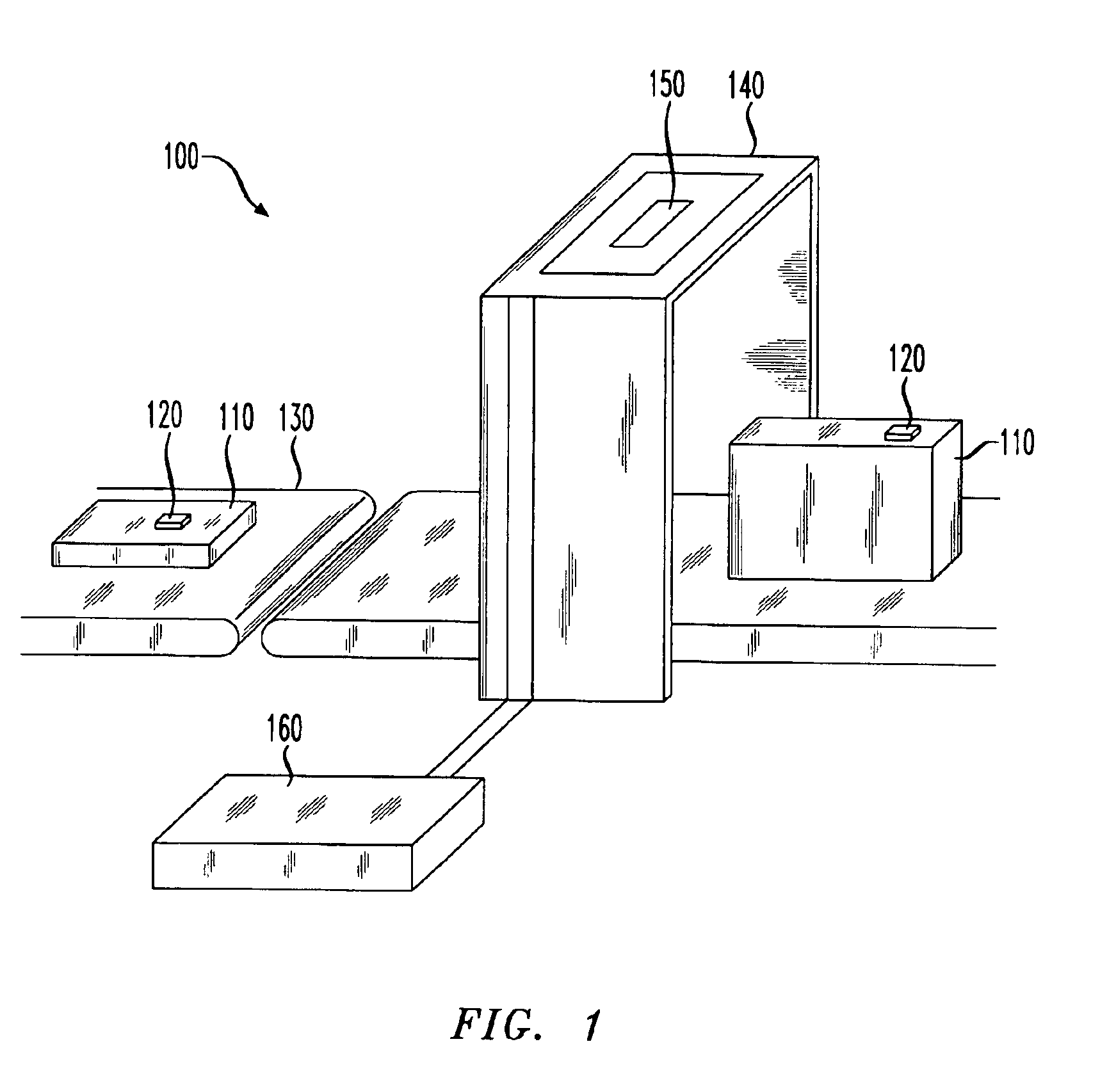
[0020]Referring initially to FIG. 1, illustrated is a representative embodiment of a SAW identification tag system 100 for identifying articles 110 by interrogating a SAW identification tag 120 located on each article 110 and decoding the response signal. For illustration purposes, a conveyor belt 130 is being used to transport articles 120 from one location to another. This is, of course, but one of a large number of potential applications where a SAW identification tag system 100 can be usefully employed. The conveyor belt 130 has an associated SAW tag reader 140 for interrogating SAW tags 120 and identifying the articles 120 or other articles to which they are attached. An antenna 150, coupled to the SAW tag reader 140, is positioned to illuminate SAW tags 120 on the conveyor belt 130 by transmitting an interrogation pulse and detects reflected signals carrying coded responses. The coded responses are transmitted to the SAW tag reader 140 where the signal will be decoded. Associa...


PUM


Abstract

A method of accommodating code collisions from multiple SAW identification tag coded response pulses. In one embodiment, the method includes: (1) separating probable candidates by time-domain; (2) classifying the probable candidates by code-division separation; (3) employing known coded identification signals to adjust the probable candidates; and (4) correlating the multiple SAW identification tag coded response pulses to identify the probable candidates for further processing.

Description

TECHNICAL FIELD OF THE INVENTION[0001]The present invention is directed, in general, to identification tags and, more specifically, to a method for accommodating code collisions from multiple surface acoustic wave (SAW) identification tag responses.BACKGROUND OF THE INVENTION[0002]A number of different electronic identification systems and devices are presently in use, ranging from ubiquitous bar code and magnetic strip systems to silicon chip radio frequency identification (“RFID”) tag systems. Because bar codes and magnetic strips have a very short effective read range and are usually read one at a time, seldom will the reading of one bar code or magnetic strip interfere with the reading of another. Although silicon chip based RFID tag systems have a longer read range than magnetic strip or bar code systems, the tags are relatively expensive and are not widely used (except for limited applications such as toll tags and security systems), which means most such prior art RFID tags w...

Claims


Application Information

Patent Timeline
Patent Type & Authority Patents(United States)
IPC IPC(8): G08B29/00H04Q5/00H04Q5/22G06FG06K7/00
CPCG06K7/0008G06K7/10029G06K19/0675G06Q10/087G06Q20/203H04B5/0062
Inventor HARTMANN, CLINTON S.BELLAMY, JOHN C.
Owner RF SAW COMPONENTS INC
Why Eureka
Try Eureka