
Electric toothbrush reduction gearbox

a technology of electric toothbrushes and gearboxes, which is applied in the direction of cleaning equipment, carpet cleaners, other domestic objects, etc., can solve the problems of complex design and many parts

Inactive Publication Date: 2005-07-26
FAST CLEAN
View PDF3 Cites 72 Cited by
  • Summary
  • Abstract
  • Description
  • Claims
  • Application Information

AI Technical Summary

Benefits of technology

[0003]It is an object of the present invention to overcome or substantially ameliorate at least one of the above disadvantages and / or more generally to provide an electric toothbrush having a motor and a reduction gearbox fitted directly to the motor to counteract the motor's output torque.

Problems solved by technology

Electric toothbrushes having a reduction gearbox have been proposed, however, they are of complex design requiring many parts.

Method used


Image

  • Electric toothbrush reduction gearbox
  • Electric toothbrush reduction gearbox
  • Electric toothbrush reduction gearbox

Examples


Embodiment Construction

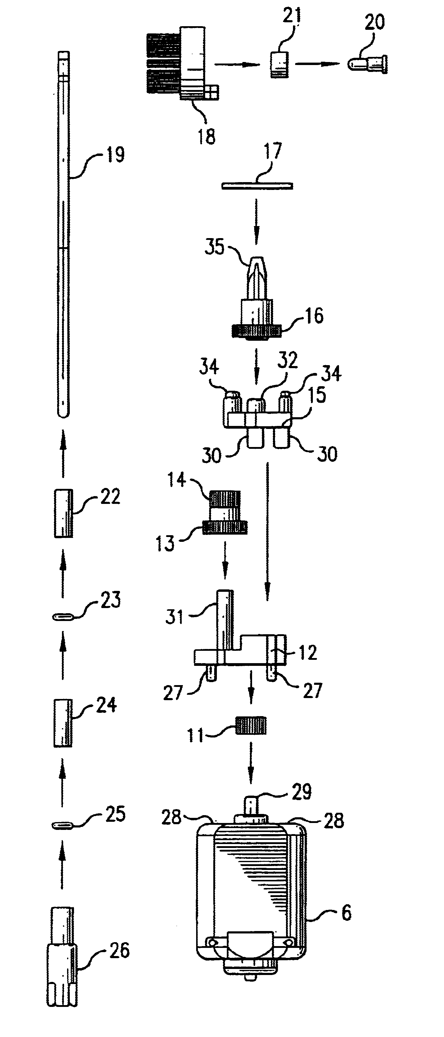
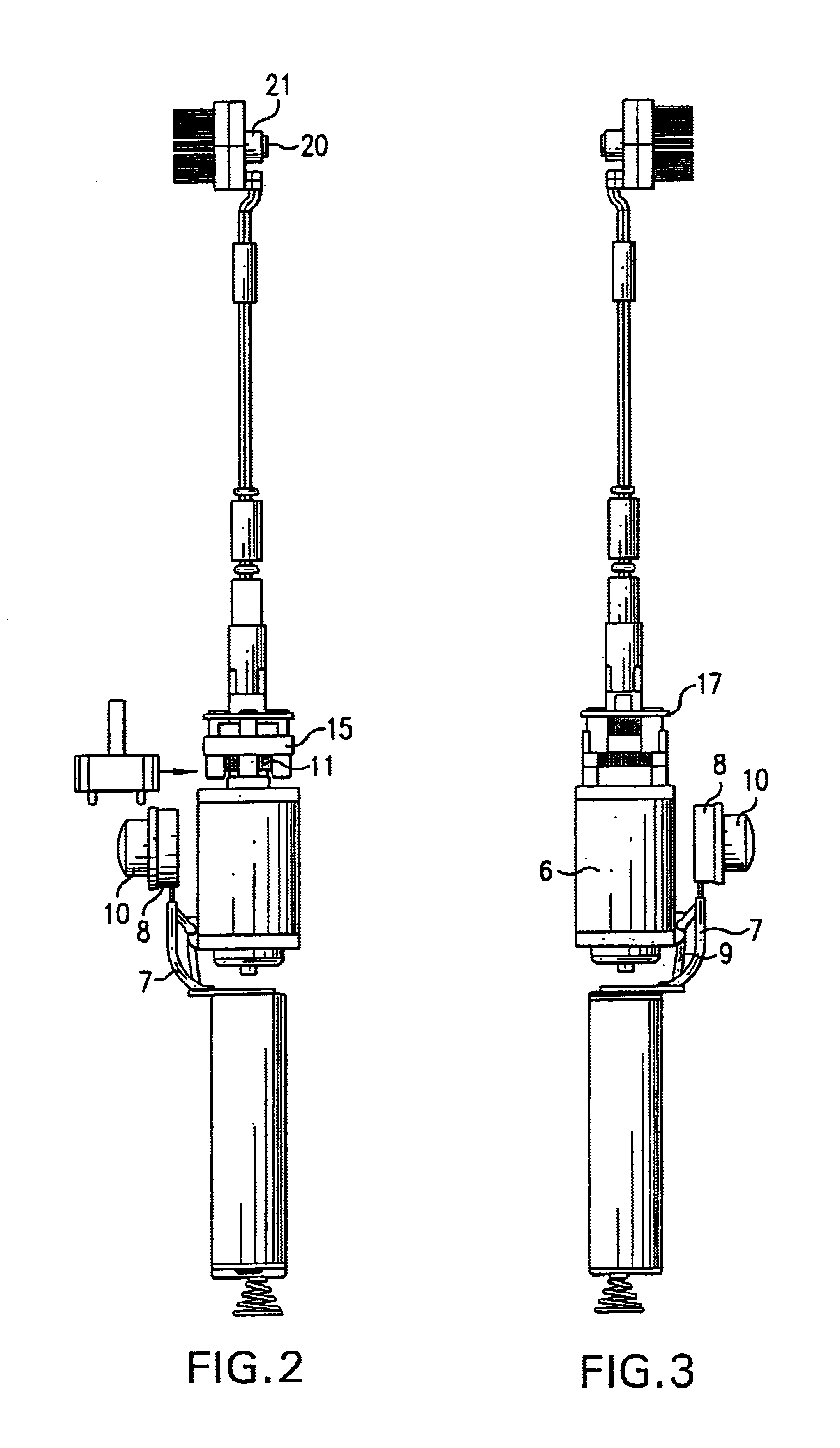
[0025]In the accompanying drawings there is schematically depicted an electric toothbrush having a plastics-moulded housing that comprises a handle H and a neck N formed integrally with the handle. Within the handle there is situated a pair of batteries 2. These batteries might be of the disposable or rechargeable type. As an alternative, a single battery might be provided. In the depicted embodiment, there are two batteries connecting series at the base by a coil spring and conductive plate arrangement 1. At the upper end of the batteries, one is connected at 3 to a positive terminal whereas the other is connected 4 to a negative terminal. Positive terminal 3 is connected via a switch wire 7 to a switch 8 that has an ON / OFF button 10. The switch 8 is connected to an electric motor 6 via a switch-motor wire 9. The positive terminal 4 is connected directly to the motor 6 via a battery-motor wire 5. The motor has in its upper surface a pair of recesses 28, between which there is situa...


PUM


Abstract

An electric toothbrush includes a handle, a bristle head and a neck extending from the handle to the bristle head. A drive shaft extends through the neck to the bristle head. A motor is situated within the handle and has a pair of spaced recesses and an output shaft situated between the recesses. A reduction gearbox receives torque from the output shaft of the motor and transmits it to the drive shaft at a reduced speed. The gearbox has a base plate having a pair of projections extending into the recesses of the motor, a cover plate fixed to the base plate and at least one gear set between the base plate and the cover plate to transmitting torque from the motor to the drive shaft.

Description

BACKGROUND OF THE INVENTION[0001]The present invention relates to an electric toothbrush having a reduction gearbox. More particularly, although not exclusively, the invention relates to an electric toothbrush having a motor driving an oscillating bristle head via a drive shaft and a reduction gearbox.[0002]Known electric toothbrushes have a handle within which there is situated a battery or batteries, an electric motor receiving power from the batteries via a switch, and a drive shaft extending through a neck of the toothbrush to an oscillating bristle head. As the motor's output is at relatively high RPM compared to the desired oscillation frequency of the bristle head, it would be desirable to reduce the output speed of the motor to drive the drive shaft at lower speed. Electric toothbrushes having a reduction gearbox have been proposed, however, they are of complex design requiring many parts. They have also been mounted to the handle independently of the motor, thereby requirin...

Claims


Application Information

Patent Timeline
Patent Type & Authority Patents(United States)
IPC IPC(8): A61C17/22A61C17/34A61C17/16A61C17/26
CPCA61C17/22A61C17/3436A61C17/26B29L2031/425
Inventor LAM, CHUN SHUN
Owner FAST CLEAN
Learn More