Grease fitting coupler

a grease fitting and coupler technology, applied in the direction of hose connections, couplings, machines/engines, etc., can solve the problems of elongating concentric tubes, affecting the use of grease or lubricating materials in some restricted areas, and affecting the use of grease or lubricating materials in and through the fittings

Inactive Publication Date: 2005-07-26
LISLE CORPORATION
View PDF7 Cites 5 Cited by
  • Summary
  • Abstract
  • Description
  • Claims
  • Application Information

AI Technical Summary

Benefits of technology

[0007]Briefly, the present invention comprises a grease fitting coupler device which includes a rigid (typically metal) body member having a counterbore opening on one side of the body member with a fitting retention slot and flange around the counterbore opening. The slot extends laterally from the coupler device. The bore is connected with a transverse inlet passage also extending laterally into the body member. Slidably positioned within the bore is a floating slide valve and fluid passage member which includes a surface that may b...

Problems solved by technology

Access to the fittings in order to pump grease or lubricating material into and through the fittings is therefore difficult.
However, because such a coupler must be used with fittings having different sizes and shapes, the frictional retention rib does not always succ...

Method used


Image

  • Grease fitting coupler
  • Grease fitting coupler
  • Grease fitting coupler

Examples


first embodiment

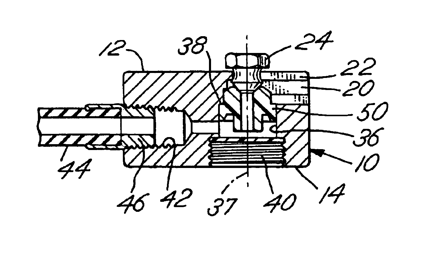
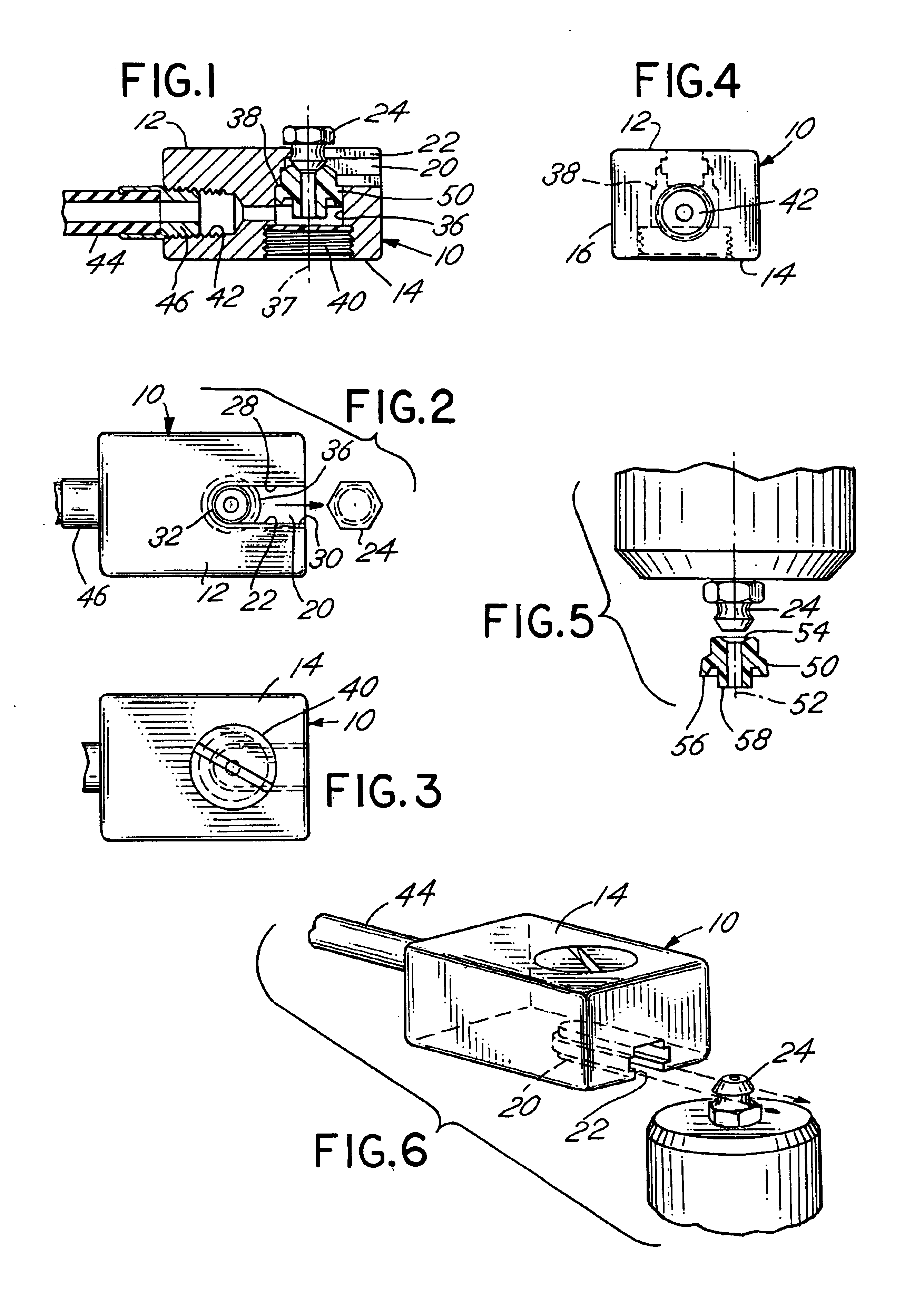
[0027]Referring to FIGS. 1-6, the coupler device includes a body member 10 which has a generally rectangular shape or configuration and includes a generally flat, top side 12 and a generally flat, bottom side 14. The sides 12 and 14 are typically parallel, however, top side 12 is preferably flat. The body member 10 further includes a lateral side 16 which is in the form of a polygon, namely, a rectangle, as depicted in FIGS. 2 and 3. The body member includes a longitudinal slot 20 in top side 12 with an outer flange 22. Slot 20 includes an arcuate inner end and extends through side 16. Thus, a zerk fitting 24 with a rounded head and a neck may slide into the slot 20 and be loosely retained from axial movement by engagement of the fitting 24 with the flange 22. The fitting 24 may have a variety of sizes and shapes. However, the flange 22 in all instances retains the filling in the slot 20 by preventing axial withdrawal. Thus, the slot 20 includes parallel sides 28 and 30 joined by an...

second embodiment

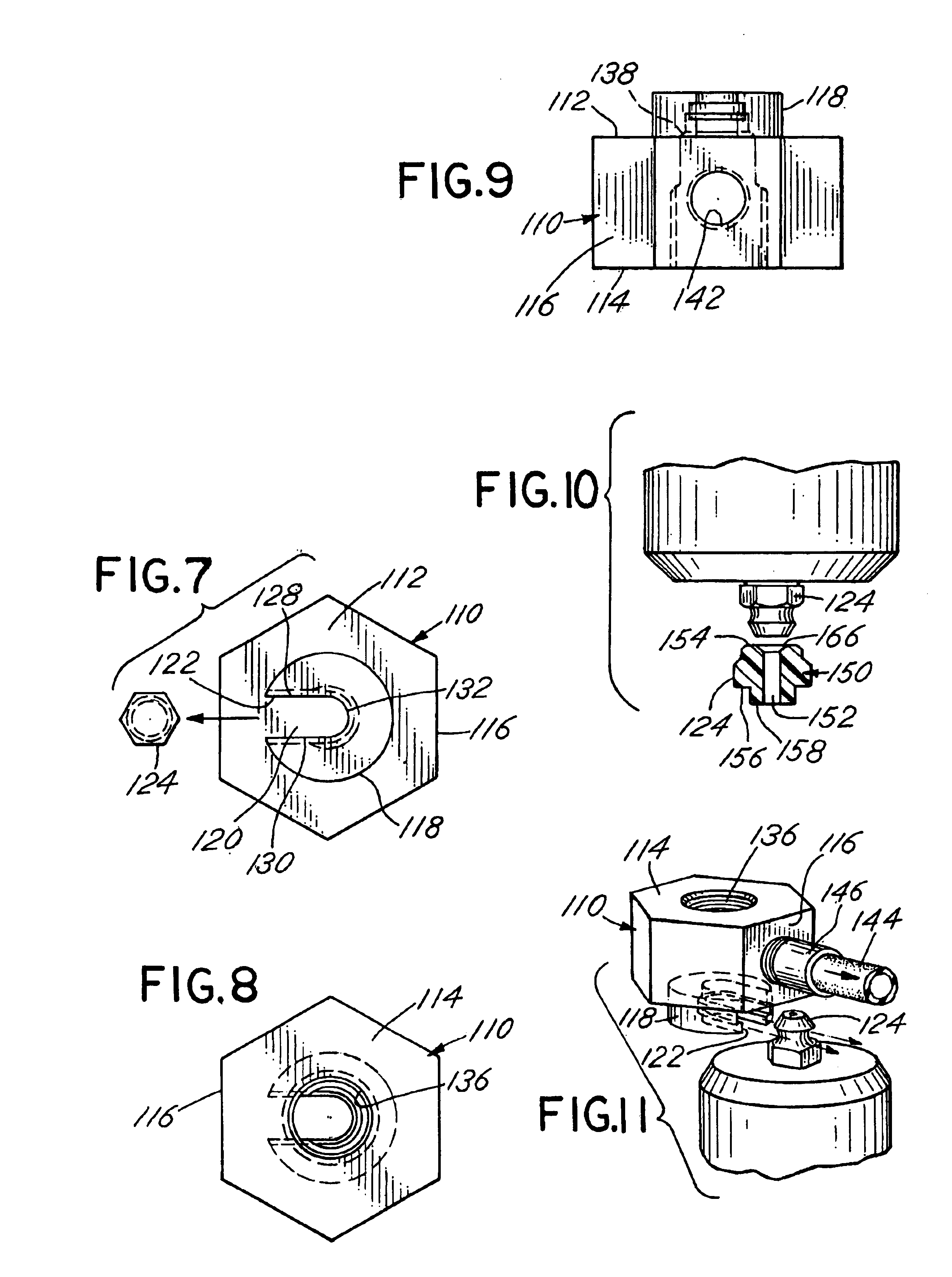
[0033]Referring to FIGS. 7-11, the coupler device includes a body member 110 which has a generally hexagonal shape or configuration and includes a generally flat, top side 112 with a center projection 118 and a generally flat, bottom side 114. The sides 112 and 114 are parallel. The body member 110 further includes a lateral side 116 which is in the form of a polygon, namely, a hexagon, as depicted in FIGS. 7 and 8. Projecting from the top side or face 112 is the fitting projection 118. The fitting projection 118 includes a longitudinal slot 120 with an outer flange 122 so that a zerk fitting 124 may slide into the slot 120 and be restrained from axial movement by engagement of the fitting 124 with the flange 122. The fitting 24 may thus be slidably inserted into the slot 120. The slot 120 includes parallel sides 128 and 130 joined by a radial connection surface 132 which fits tightly against the outside of the circular cross section shaft of a fitting 124.

[0034]The body member 110 ...


PUM


Abstract

A grease fitting coupler device includes a body member with a slot on one side for engagement with a fitting and a series of passages through the body member connected with a lubrication source. A slidable valve member within the body member is pressurized against the fitting to seal the coupler device while lubricating fluid is passed therethrough.

Description

BACKGROUND OF THE INVENTION[0001]In a principal aspect, the present invention relates to a coupler device which may be utilized in restricted access areas by attachment to a grease fitting or “zerk” fitting.[0002]When servicing a vehicle such as an automobile or truck, it is typically necessary to couple a source of grease to the grease fittings, often termed zerk fittings, located at strategic positions on the vehicle, for the injection of grease or lubricating materials. Often, the zerk fittings are positioned in restricted spaces. Access to the fittings in order to pump grease or lubricating material into and through the fittings is therefore difficult. As a result, there has developed the need for a mechanism or device for attachment or coupling to a grease fitting from the side of the grease fitting rather than from the top of the fitting.[0003]One known type of device comprises a molded urethane coupler having an open slot at one end. The zerk fitting may then be inserted into...

Claims


Application Information

Patent Timeline
IPC IPC(8): F16N21/04F16N21/00
CPCF16N21/04
Inventor PLOEGER, RANDALL J.
Owner LISLE CORPORATION
Why Eureka
Try Eureka