Rolling-lobe air spring having a support bell

a technology of air spring and support bell, which is applied in the direction of shock absorbers, mechanical devices, transportation and packaging, etc., can solve the problems of no guarantee of reliably tight seat and stability, and achieve the effect of tight seat and high stiffness

Inactive Publication Date: 2005-07-26
CONTINENTAL AG
View PDF20 Cites 7 Cited by
  • Summary
  • Abstract
  • Description
  • Claims
  • Application Information

AI Technical Summary

Benefits of technology

[0003]It is an object of the invention to provide a support bell for an air spring which provides high stiffness and a tight seat.

Problems solved by technology

Problems with respect to stability result from the soft clamping of the rolling-lobe flexible member when the air spring module as a unit is articulatedly connected to the body of a vehicle or to a connecting rod.
Also, no reliably tight seat is ensured because of the intermediate connection of the end of the rolling-lobe flexible member.

Method used


Image

  • Rolling-lobe air spring having a support bell
  • Rolling-lobe air spring having a support bell
  • Rolling-lobe air spring having a support bell

Examples


Embodiment Construction

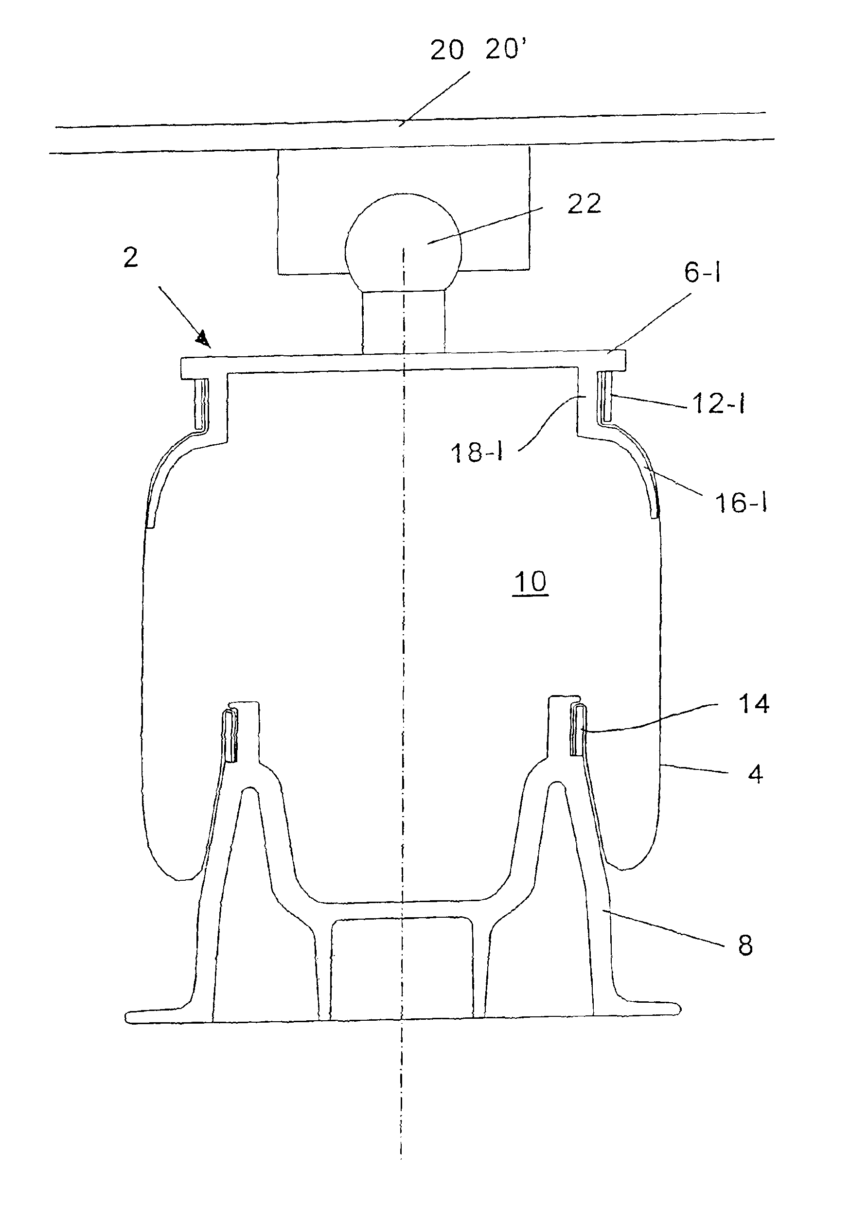
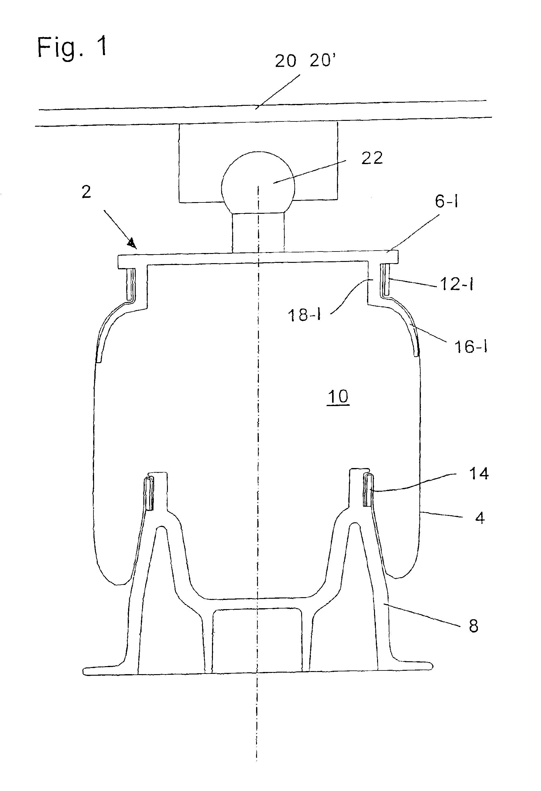
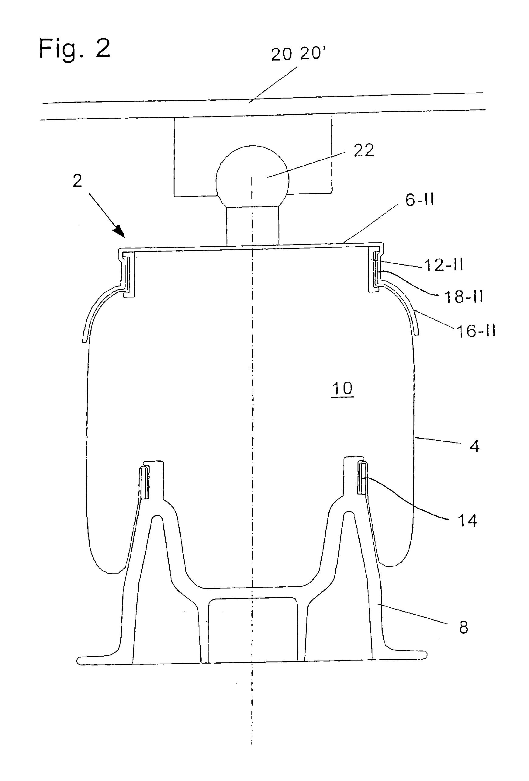
[0015]The two embodiments of the air spring 2 according to the invention shown in FIGS. 1 and 2 each comprise a rolling-lobe flexible member 4 which is connected at its upper end to a cover (6-I or 6-II) and is connected pressure-tight at its lower end to a roll-off piston 8. The rolling-lobe flexible member encloses a pressure space 10 of variable volume. The designations “upper” and “lower” refer only to the views presented in the drawings. An opposite installation in a motor vehicle is easily possible. The end attachment of the flexible member 4 to the cover (6-I or 6-II) and the piston 8 is provided by clamp rings (12-I or 12-II) and clamp ring 14.

[0016]For lateral guidance, the rolling-lobe flexible member 4 is provided with a support bell (16-I or 16-II) in the region of the corresponding cover (6-I or 6-II).

[0017]What is special in the air spring 2 of the invention is that the covers (6-I or 6-II) and support bells (16-I or 16-II) are configured as a single piece. More specif...


PUM


Abstract

A rolling-lobe air spring (2) includes a cover (cover plate, 6-I or 6-II), a roll-off piston (8) and a rolling-lobe flexible member (4). A support bell (16-I or 16-II) is provided in order to solve stability problems. The support bell (16-I or 16-II) is rigidly connected to the cover (6-I or 6-II) in order to provide a guide of high stiffness to the rolling-lobe flexible member. The support bell (16-I or 16-II) is rigidly connected to the cover (6-I or 6-II) and can be arranged within or outside of the cover (6-I or 6-II). For an inner-lying support bell (16-I) the upper end of the rolling-lobe flexible member is attached to the throat region (18-I) of the support bell (16-I) with the aid of a clamp ring (12-I) applied from the outside. For an outside-lying support bell (16-II), the throat region (18-II) of the support bell (16-II) is deformed against the upper end of the rolling-lobe flexible member and against a support ring (12-II) disposed therebelow.

Description

BACKGROUND OF THE INVENTION[0001]Only low torques can be transmitted between the rolling-lobe flexible member and the cover in rolling-lobe air springs without a support bell. More specifically, the clamping of the rolling-lobe flexible member functions as a joint. Problems with respect to stability result from the soft clamping of the rolling-lobe flexible member when the air spring module as a unit is articulatedly connected to the body of a vehicle or to a connecting rod.[0002]Air springs have been increasingly provided with support bells in order to solve the stability problem. In the air spring described in German patent publication 4,325,576, the support bell is connected indirectly to the air spring cover with the upper end of the flexible member being connected therebetween. A support bell, which is connected in this manner indirectly to the cover, provides only a slight support function because the connection of the support bell to the air spring cover is soft and flexible....

Claims


Application Information

Patent Timeline
Patent Type & Authority Patents(United States)
IPC IPC(8): F16F9/05F16F9/02F16F9/04B60G11/28
CPCB60G11/28F16F9/0454F16F9/05B60G2204/126B60G2204/416
Inventor OLDENETTEL, HOLGERGLEU, JENS-UWE
Owner CONTINENTAL AG
Why Eureka
Try Eureka