

Flame-resistant wick holder for candle
a wick and flame-resistant technology, applied in the field of candle making, can solve the problems of glass containers breaking, carbon balls forming, metal tins scorching paint off the tin sides and char surfaces, etc., and achieve the effect of eliminating flashover
Inactive Publication Date: 2005-08-02
BEAUTYAVENUES
View PDF35 Cites 60 Cited by
- Summary
- Abstract
- Description
- Claims
- Application Information
AI Technical Summary
Benefits of technology
[0025]It is an object of the present invention to provide a no
Problems solved by technology
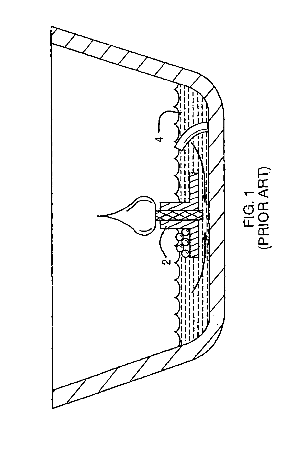
This phenomenon is called “flash” or “flashover” and is a problem especially with candles formed or supported in containers.
During flashover, the temperature within the candle can be elevated to at least 1200° F. This excessive heat can cause glass containers to break, and it can cause metal tins to scorch the paint off the tin sides and char surfaces on which they are resting.
An additional problem is that carbon balls may form during burning and fall into the wax pool at the bottom of the candle, or the user may allow matches or wick trimmings to fall to the bottom.
These foreign objects may aggravate the flashover problem by becoming secondary wicks if they are ignited by the candle flame.
When the depth of the molten wax 4 is sufficiently small, the flashover problem can occur.
Flashover is a problem which causes significant damage and harm.
Flashover can result in house fires and burns to people who use candles decoratively.
When the candle flame nears the safety layer and causes it to melt, the wax in the safety layer begins to block the wick, subsequently resulting in the candle flame being extinguished du
Method used
View moreImage
Smart ImageViewing Examples

Examples
 PUM
 Abstract
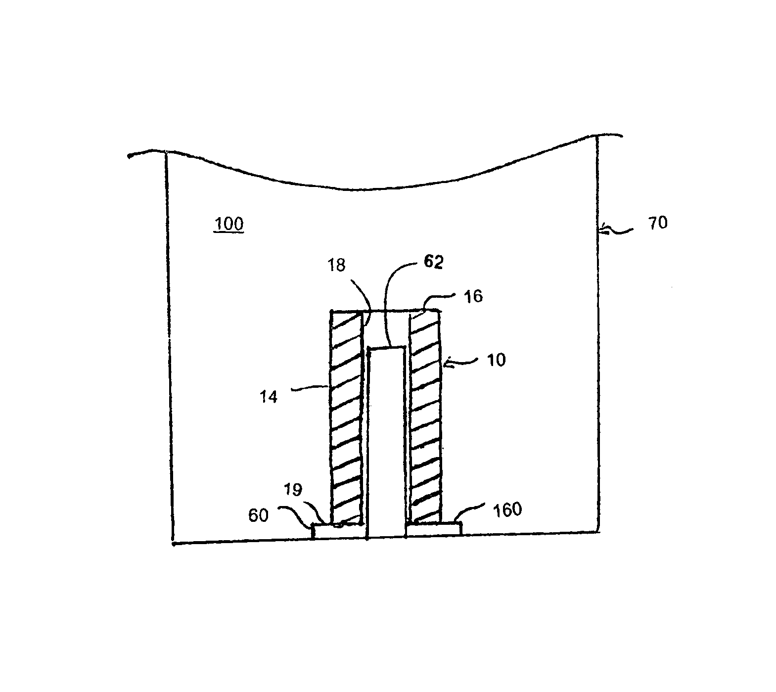
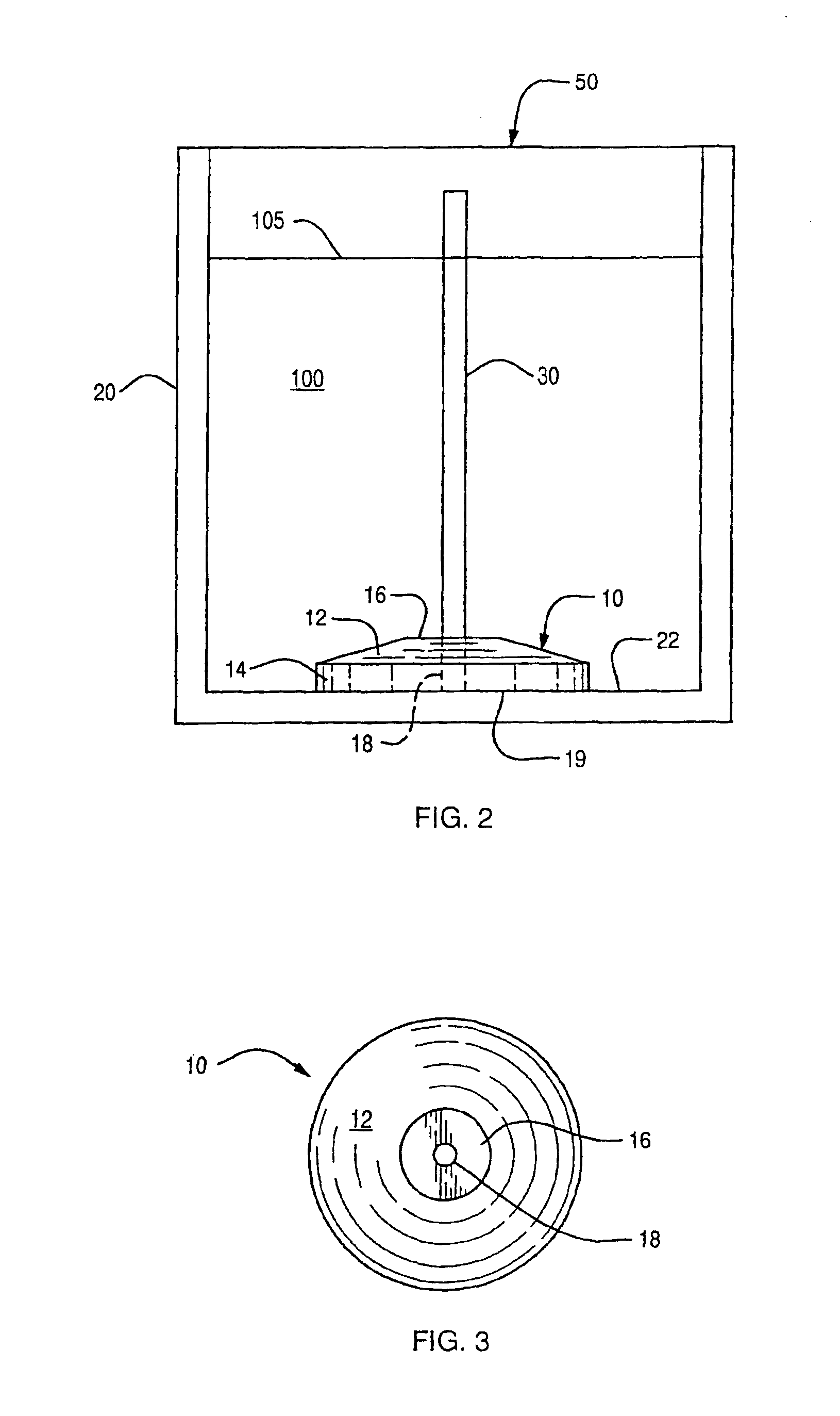
A flame-retardant wick holder for a candle is made of a material having a UL-94 vertical burn test rating of at least V-0, including polymers and ceramics. The wick holder supports a wick at the bottom of a candle. The wick holder material causes the flame on the wick to extinguish when it reaches the holder, thereby preventing flashover of the residual candle fuel at the end of the candle useful life. One version of the holder has a cylindrical sleeve fit over a wick clip holding the lower end of the wick. The cylindrical holder is well adapted for use in pillar-type candles.
Description
CROSS REFERENCE TO RELATED APPLICATIONS[0001]This application is a continuation-in-part application of U.S. patent application Ser. No. 10 / 257,201 filed on Oct. 9, 2002, now abandoned, which is the National Phase of International Application PCT / US02 / 26313 filed Aug. 16, 2002, which claims priority of U.S. patent application Ser. No. 10 / 131,943 filed Apr. 25, 2002, now U.S. Pat No. 6,773,484, which is a continuation-in-part application of U.S. patent application Ser. No. 09 / 931,826 filed Aug. 17, 2001, now U.S. Pat. No. 6,508,644, the entirety of each of which is hereby incorporated by reference.FIELD AND BACKGROUND OF THE INVENTION[0002]The present invention relates generally to the field of candle making and in particular to a new and useful holder for a wick which extinguishes the candle flame at the end of the candle useful life.[0003]Candle wicks function by capillary action drawing a fuel from a pool up through the wick to the flame. The fuel used in known candles may be paraf...
Claims
Login to View More Application Information
Patent Timeline
 IPC IPC(8): F23D3/00F23D3/08F23D3/16F23D3/26C11C5/00
CPCC11C5/006F23D3/08F23D3/16F23D3/26
InventorPESU, BRADLEY D.ROMANO, JOSEPH P.DESTEFANO, FABIANTHOMAS, CHERIYAN B.
OwnerBEAUTYAVENUES