Low-visual noise, jitterized pulse width modulation brightness control circuit

a pulse width modulation and low-visual noise technology, applied in the direction of automatic control, instruments, light sources, etc., can solve the problems of back light signal interference, glistening on the display, and requiring a higher cost, so as to reduce visual interference and low-visual noise pulse width modulation

Inactive Publication Date: 2005-08-02
BEYOND INNOVATION TECH
View PDF8 Cites 22 Cited by
  • Summary
  • Abstract
  • Description
  • Claims
  • Application Information

AI Technical Summary

Benefits of technology

[0012]An object of the present invention is to provide a low visual noise pulse width modulation (PWM) brightness control circuit by adjusting the frequency or period of the brightness control pulse signal and maintain the average operational frequency or period to reduce the visual interference generated by jitterized pulse width modulation brightness control.
[0013]The present invention provides a low visual noise, jitterized pulse width modulation brightness control circuit, for adjusting a brightness of a fluorescent lamp in a liquid crystal display comprising: a brightness control signal generating unit receiving a brightness adjusting signal and generating a brightness control signal in response to the brightness adjusting signal, the brightness control signal having an operational period varying in a predetermined range; and a inverter coupled to the brightness control signal generating unit driving the fluorescent lamp in response to the brightness control signal.
[0019]Therefore, the low visual noise dimmer control circuit of the present invention can reduce the interference due to adjustment of the current beam density by adjusting the frequency or period of the brightness control signal and maintain the average operational frequency or frequency of the brightness control signal.

Problems solved by technology

Because the frequency of the brightness control signal is fixed based on the required brightness, when the lamp is used for LCD back light, the back light signal would interfere the vertical and horizontal video signals due to the frequency difference.
Further, the frequency of switching the inverter also affects the power source of the inverter, which causes the power source to generate the ripples having the same frequency as the brightness control signal.
The generated ripples also affect the scan signal, which causes glistening on the display.
However, it requires a higher cost.
However, for a large size LCD, it is more and more difficult to achieve a low-noise and a wide dimming range lamp solution.

Method used


Image

  • Low-visual noise, jitterized pulse width modulation brightness control circuit
  • Low-visual noise, jitterized pulse width modulation brightness control circuit
  • Low-visual noise, jitterized pulse width modulation brightness control circuit

Examples


Embodiment Construction

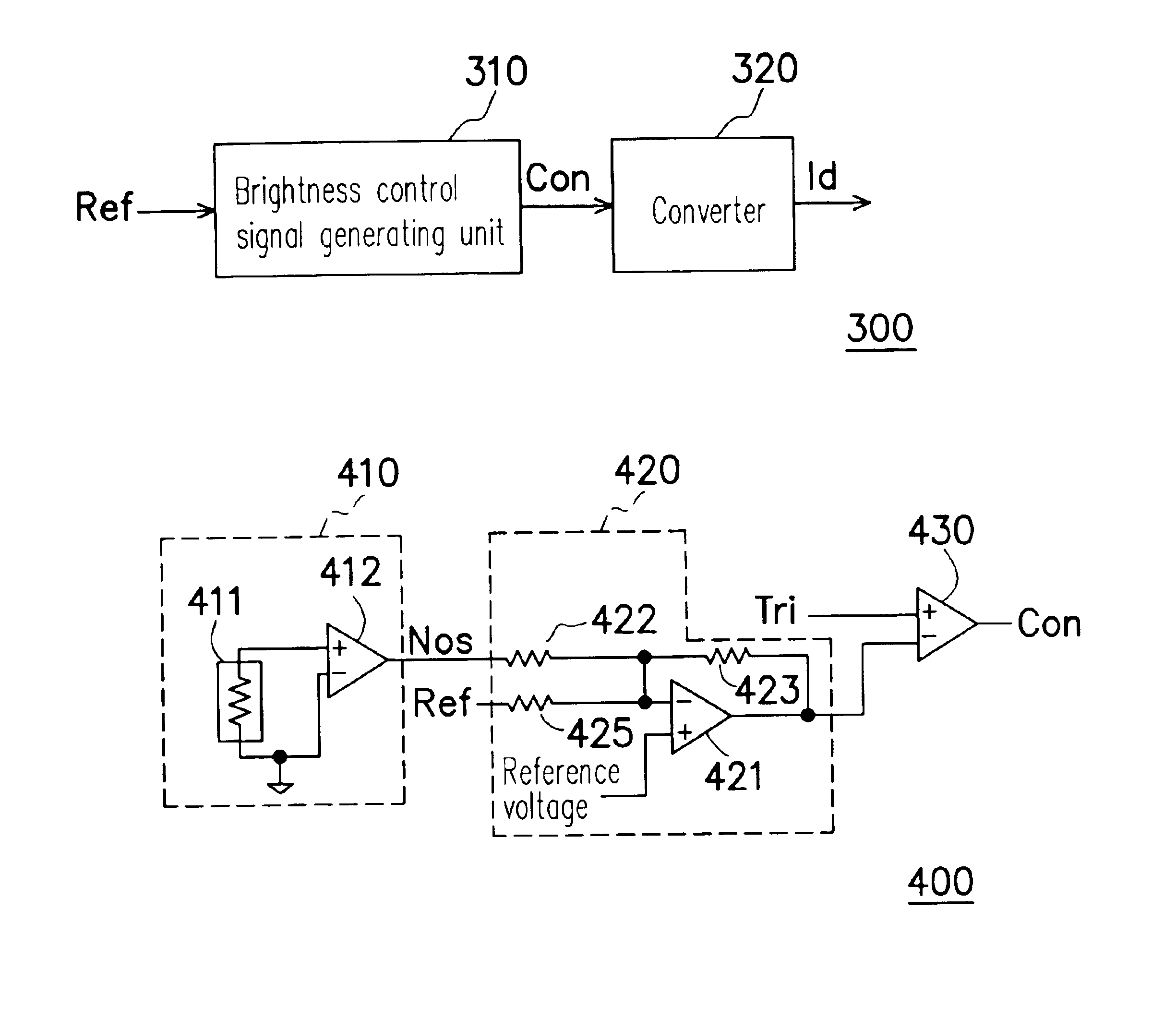
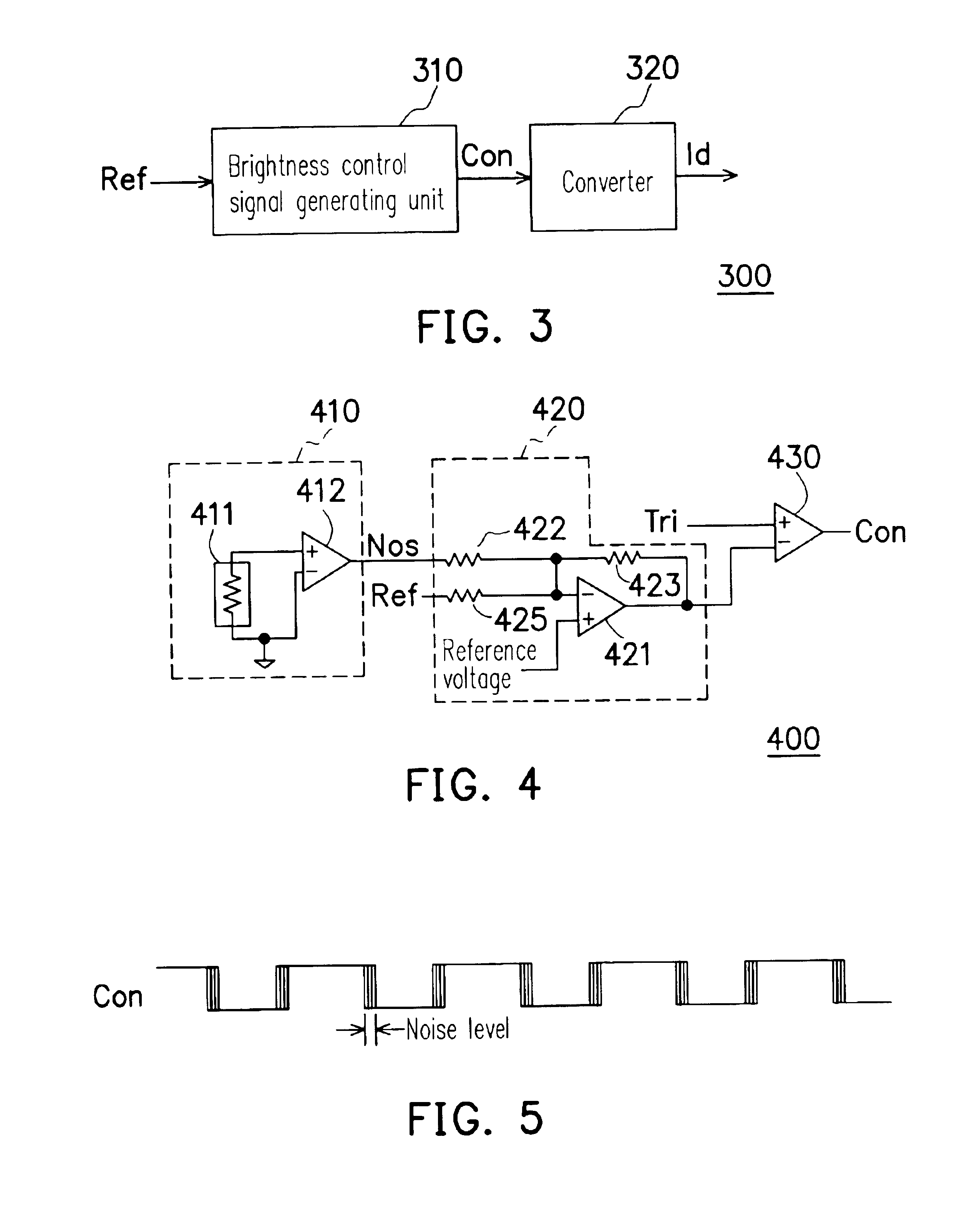
[0027]FIG. 3 is a block diagram of the low visual noise, jitterized pulse width modulation brightness control circuit in accordance with a preferred embodiment of the present invention. The low visual noise, jitterized pulse width modulation brightness control circuit 300 is suitable for adjusting the brightness of a fluorescent lamp (not shown) in a liquid crystal display.

[0028]As shown in FIG. 3, the low visual noise, jitterized pulse width modulation brightness control circuit 300 includes a brightness control pulse signal generating unit 310 and an inverter 320. The brightness control pulse generating unit 310 receives a brightness adjusting signal Ref and generates a brightness control pulse signal Con in response to the brightness adjusting signal Ref. To prevent the visual interference due to adjustment of the current beam density, the brightness control pulse signal Con has a duty cycle or frequency varying in a predetermined range so that the brightness control pulse signal...


PUM

PropertyMeasurementUnit
frequencyaaaaaaaaaa
brightnessaaaaaaaaaa
frequencyaaaaaaaaaa

Abstract

A low visual noise, jitterized pulse width modulation brightness control circuit is provided. The circuit uses a brightness control signal generating unit to receive a brightness adjusting signal and to generate a brightness control signal in response to the brightness adjusting signal. The brightness control pulse signal has a duty cycle or frequency varying in a predetermined range. An inverter coupled to the brightness control signal generating unit drives the fluorescent lamp in response to the brightness control pulse signal to reduce the visual interference due to the adjustment of the current beam density.

Description

CROSS-REFERENCE TO RELATED APPLICATION[0001]This application claims the priority benefit of Taiwan application Ser. No. 92125460, filed on Sep. 16, 2003.BACKGROUND OF THE INVENTION[0002]1. Field of the Invention[0003]This invention generally relates to a dimmer control circuit, and more particularly to a low visual noise dimmer control circuit by adjusting current beam density.[0004]2. Description of Related Art[0005]Liquid crystal displays (LCD) have been widely used to replace the conventional CRT displays. As the semiconductor manufacturing technology advances, LCD has several advantages such as low power consumption, light weight, high resolution, high color saturation, and longer lifetime, and can be used in state-of-the-art electronic devices such as digital cameras, notebook computers, desktop computers, mobile phones, personal digital assistant (PDA), global positioning system (GPS), etc.[0006]Because LCD is not self-emitting, a cold cathode fluorescent lamp (CCFL) is used a...

Claims


Application Information

Patent Timeline
Patent Type & Authority Patents(United States)
IPC IPC(8): G02F1/13G02F1/133G05F1/00G09G3/18H03L7/00H05B41/282H05B41/39H05B41/28H05B41/392G09G3/34H05B41/38
CPCH05B41/3921G09G3/3406G09G2320/0247H05B41/38
Inventor YU, ANDRECHANG, JEFFREYHUANG, BILL
Owner BEYOND INNOVATION TECH
Why Eureka
Try Eureka