Zoom lens, camera, and mobile information terminal

a technology of zoom lens and information terminal, which is applied in the direction of optics, instruments, optics, etc., can solve the problems of insufficiently satisfying the requirement for a wider angle of view, performance significantly deteriorating in a high frequency domain, and insufficiently satisfying the requirement for high density

Inactive Publication Date: 2005-08-02
RICOH KK
View PDF38 Cites 26 Cited by
  • Summary
  • Abstract
  • Description
  • Claims
  • Application Information

AI Technical Summary

Problems solved by technology

However, the configurations disclosed above cannot sufficiently satisfy the requirement for a wider angle of view, since the half angle of view at the short focal-length side is as narrow as 30 degrees.
With such a dark lens, when the size of one pixel decreases, since the image capturing device such as a charge coupled device (CCD) has a high density, the performance considerably deteriorates in a high frequency domain.
Therefore, it cannot satisfy the requirement for the high density sufficiently.
However, the magnification is not larger than 2×, and hence it cannot sufficiently satisfy the requirement for the high magnification.
However, the half angle of view is only 25 degrees or less, and hence it is still not sufficient for obtaining a wide angle.
H6-94997 includes the whole basic configuration in this case, but does not propose a configuration requirement sufficient for achieving small size.
H10-62687 aims at miniaturization by reducing the number of pieces, but sufficient aberration correction is not performed, and does not have performance that can correspond to an image capturing device with 3,000,000 to 5,000,000 pixels.
H11-258507 is relatively small, and the imaging performance is better than those described above, but the half angle of view is still about 33 degrees, and hence it is still not sufficient for achieving wide angle.
However, the magnification obtained is about 3×, which is not a sufficient value for the recent requirement for high magnification.
However, a magnification of about 6× can be obtained, which is still not sufficient considering the recent requirement for high magnification.

Method used


Image

  • Zoom lens, camera, and mobile information terminal
  • Zoom lens, camera, and mobile information terminal
  • Zoom lens, camera, and mobile information terminal

Examples


first embodiment

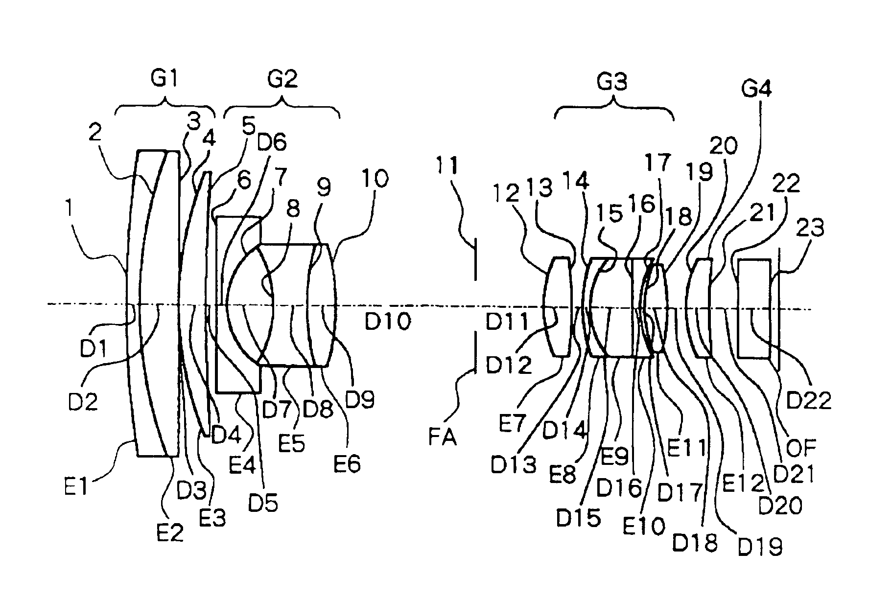
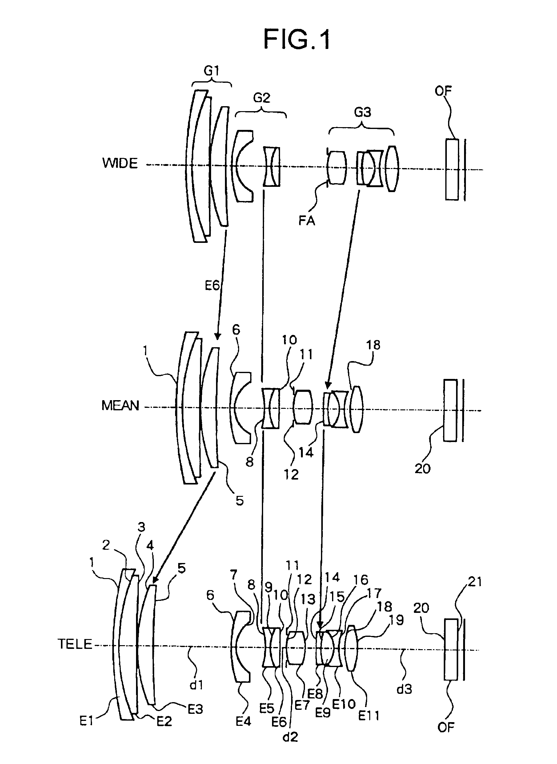
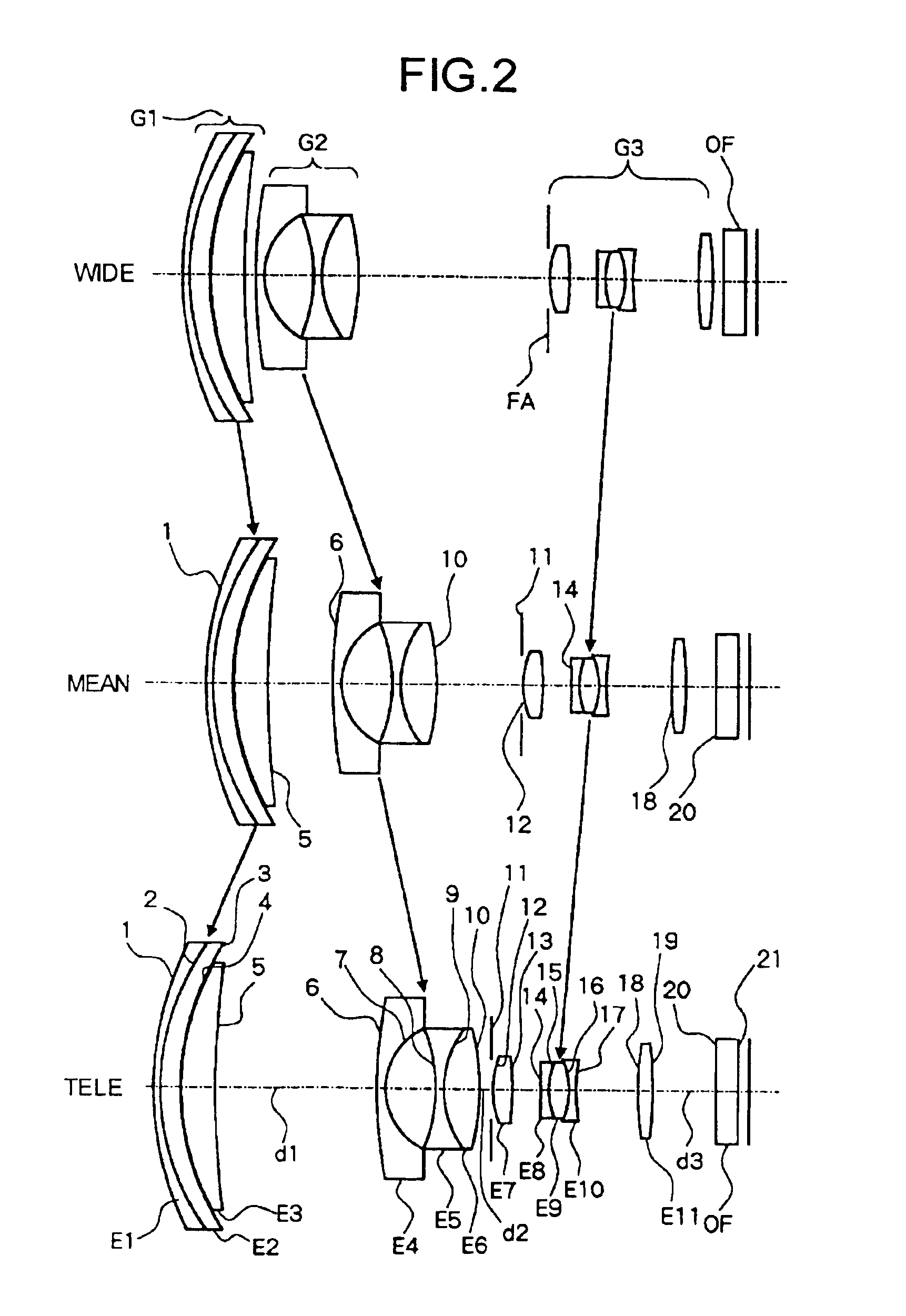
[0107]The zoom lens includes a first group optical system having a positive refracting power, a second group optical system having a negative refracting power, a third group optical system having a positive refracting power, and a diaphragm that moves toward an object side integrally with the third group optical system. The first group optical system, the second group optical system, and the third group optical system are sequentially arranged from the object side toward an image side. At least the first group optical system and the third group optical system moves in such a manner that a distance between the first group optical system and the second group optical system becomes minimum at a short focal-length side, and a distance between the second group optical system and the third group optical system becomes minimum at a long focal-length side. The third group optical system includes a triplet lens formed by sequentially bonding a negative lens, a positive lens, and a negative ...

second embodiment

[0123]The camera is for recording an image of a subject via the zoom lens according to the present invention. By employing the zoom lens in a film camera, a digital still camera, or a digital video camera, a compact camera of an electric power saving type, which can obtain a high variable power and high image quality, can be obtained. Further, it is desired that the light-receiving image capturing device that receives light of the subject image by the zoom lens have 3,000,000 pixels or more. As the number of pixels increases, the light-receiving image capturing device can improve the recording density of the subject image. Therefore, by having 3,000,000 pixels or more, even when the subject image recorded by the camera of the present invention is printed out, an output image having the quality the same as that of the conventional film camera or higher can be obtained.

[0124]FIG. 16 is a schematic diagram of a digital camera according to a second embodiment of the present invention, ...

third embodiment

[0133]FIG. 18 is a schematic diagram of a digital camera according to the present invention, which has a single-lens reflex-type optical finder

[0134]The mobile information terminal further includes a communication interface (I / F) 64 for transmitting image data shot and recorded by the camera to a personal computer PC or the like via a communication system, in addition to the configuration of the camera as illustrated in FIG. 18, to constitute the camera unit.

[0135]In such a mobile information terminal, the mobile information terminal can be made considerably small, by using the camera as a built-in camera unit, thereby obtaining high quality recorded data.

[0136]A fourth embodiment of the present invention explains the zoom lens according to the present invention. At first, a fundamental configuration of the zoom lens according to the fourth embodiment is explained, followed by a specific configuration of the zoom lens according to the fourth embodiment, by enumerating specific numer...


PUM


Abstract

A first group optical system having a positive refracting power, a second group optical system having a negative refracting power, and a third group optical system having a positive refracting power are sequentially arranged from an object side toward an image side. At least the first group optical system and the third group optical system move so that a distance between the first group optical system and the second group optical system becomes minimum at short focal-length side, and a distance between the second group optical system and the third group optical system becomes minimum at long focal-length side. The third group optical system includes a triplet lens formed with a negative lens, a positive lens, and a negative lens.

Description

CROSS-REFERENCE TO RELATED APPLICATIONS[0001]The present document incorporates by reference the entire contents of Japanese priority documents, 2003-075660, 2003-076534 and 2003-076660 filed in Japan on Mar. 19, 2003 and 2003-126882 filed in Japan on May 2, 2003.BACKGROUND OF THE INVENTION[0002]1) Field of the Invention[0003]The present invention relates to a compact zoom lens suitable for a video camera and a still camera, a camera using the zoom lens as a shooting optical system, and a mobile information terminal using the zoom lens as a shooting optical system in its camera unit.[0004]2) Description of the Related Art[0005]Since requirements for a higher magnification, a wider angle of view, and a higher resolving power are increasing in the zoom lens for a video camera and a still camera, it is essential to reduce whole length and outer diameter of the lens, as well as the number of lenses, in order to realize small size, light weight, and low cost. As such a zoom lens, a zoom c...

Claims


Application Information

Patent Timeline
Patent Type & Authority Patents(United States)
IPC IPC(8): G02B15/163G02B15/173
CPCG02B15/173G02B15/145129
Inventor NISHINA, KIICHIROTATSUNO, HIBIKIONO, NOBUAKI
Owner RICOH KK
Why Eureka
Try Eureka