Tool head

Inactive Publication Date: 2005-08-09
ANDREAS STIHL AG & CO KG
View PDF3 Cites 15 Cited by
  • Summary
  • Abstract
  • Description
  • Claims
  • Application Information

AI Technical Summary

Benefits of technology

[0022]Pursuant to a further embodiment of the present invention, the centering element also fulfills the objective of providing protection against losing the engagement plate. For this purpose, in the axial direction the engagement plate is placed upon the tool shaft in a manner free of seizing, and is held by the centering element in the direction of the free end of the tool shaft. This permits a simple assembly or removal of the engagement plate by placement upon or removal essentially without a tool. Furthermore, during exchange of the cutter t

Problems solved by technology

Due to the small size of the centering element, even if a hard and heavy material is selec

Method used


Image

  • Tool head
  • Tool head
  • Tool head

Examples


Example

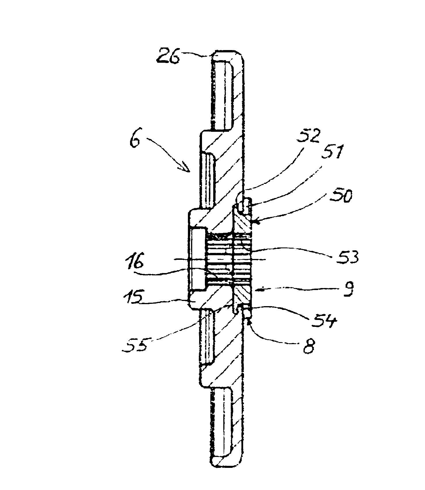
[0026]Referring now to the drawings in detail, FIG. 1 shows a tool head having mounted thereon a cutter tool 1, which in the illustrated embodiment is a steel cutting blade, but which could also be a filament reel, a circular saw blade, etc. The cutter tool 1 is driven by a tool shaft 4 that is rotatably mounted in two bearing means 3 in a head housing 2. The housing 2 has a shank 21 that is disposed at an angle to the shaft axis 12 and through which is guided a non-illustrated, motor-driven drive shaft. In the illustrated embodiment, the housing 2 and the shank 21 are monolithic. Disposed in the region of the connection location between the head housing 2 and the shank 21 is a bevel gear arrangement 22 for driving the tool shaft 4. Disposed in the region of the free end 18 of the tool shaft 4 is a thread 23, with an external toothing 17 being provided between the thread 23 and the bearing means 3. An engagement plate 6 and a centering element 9 are placed upon the tool shaft 4 in t...


PUM

PropertyMeasurementUnit
Weightaaaaaaaaaa
Hardnessaaaaaaaaaa

Abstract

A tool head for a motor-driven, manually guided implement for receiving a rotatable cutter tool is provided. The tool head comprises a housing in which is provided a tool shaft that is rotatably mounted via bearings. Secured on the tool shaft so as to turn with it is a tool carrying mechanism for the cutter tool. This tool carrying mechanism includes an engagement plate having an engagement surface, which is oriented perpendicular to the axis of the shaft, and a centering shoulder. The engagement plate and a centering element having the centering shoulder are embodied as separate components. The engagement plate is of light weight construction and is positively connected with the tool shaft. The centering element is made of a material, the hardness of which is adapted to the cutter tool.

Description

CROSS-REFERENCE TO RELATED APPLICATIONS[0001]This application is a continuation-in-part of application Ser. No. 09 / 668,434 filed Sep. 22, 2000, now abandoned.BACKGROUND OF THE INVENTION[0002]The present invention relates to a motor-driven, manually guided implement for receiving a rotatable cutter tool.[0003]Tool heads, especially for rapidly rotating cutter tools, such as with brush cutters, edgers, cut-off saws, etc., are constructed pursuant to light weight standards taking into consideration handling ability, low centrifugal forces, and the avoidance of vibration problems. With such tool heads, rapidly rotating tools such as blades or filament reels, in order to avoid imbalances, are oriented at right angles and centrally relative to the longitudinal axis of the tool shaft by means of a tool carrying mechanism. For this purpose, the tool carrying mechanism is provided with an engagement plate having a contact surface that is oriented perpendicular to the shaft axis and against w...

Claims


Application Information

Patent Timeline
IPC IPC(8): B24B23/02B24B23/00B24B45/00
CPCB24B23/02B24B45/00Y10T83/9377
Inventor BARTMANN, UDOSCHIERLING, ROLANDFRIEDRICH, REINHARD
Owner ANDREAS STIHL AG & CO KG
Why Eureka
Try Eureka