Forging press

A mechanical and forging technology, applied in the field of forging machinery, can solve the problems affecting the working accuracy of the press, the complex clutch structure, the unbalanced force of the crankshaft, etc., to improve the transmission accuracy and service life, light weight and good sealing effect.

Inactive Publication Date: 2020-06-09
湖北鑫锤锻造科技有限公司
View PDF1 Cites 0 Cited by
  • Summary
  • Abstract
  • Description
  • Claims
  • Application Information

AI Technical Summary

Problems solved by technology

[0002] At present, the mechanical press clutch and brake are set together on the end of the crankshaft close to the flywheel. Patent No. ZL99805307.4 discloses a mechanical press clutch brake device; the clutch and brake of this mechanical press clutch brake device are integrated and arranged on the crankshaft. On the end close to the flywheel, since the clutch and the brake are integrated and arranged on the end of the crankshaft close to the flywheel, the force on both ends of the crankshaft is unbalanced, which makes the crankshaft supporting parts, such as bearings, prone to failure, shortens the service life, and affects the working accuracy of the press
When this mechanical press clutch brake device is used in a high-speed mechanical press, its shortcomings are even more serious. The mechanical press clutch brake device uses a hydraulic cylinder switching mechanism to switch the clutch and brake, and the structure is complex and prone to leakage. leak
Moreover, existing clutches have disadvantages such as complex structure, large space requirements (placed outside the flywheel), large braking inertia (clutches are mainly placed on the crankshaft), etc.

Method used


Image

  • Forging press
  • Forging press

Examples


Embodiment 1

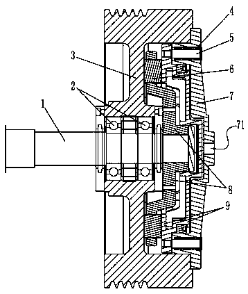
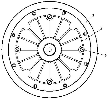
[0011] As shown in Figure 1 and Figure 2, a forging machine includes a crankshaft 1, a brake is installed on one end of the crankshaft 1, and a clutch is installed on the other end of the crankshaft 1, and the clutch includes a flywheel that is sleeved on the crankshaft 1 in turn 3. The driven shaft sleeve 8 and the driving disc 9, the flywheel 3 is installed on the crankshaft 1 through the bearing 2, the driven shaft sleeve 8 and the driving disc 9 are arranged in the cavity of the flywheel 3, and a housing 7 is fixedly connected to the outside of the cavity of the flywheel 3 , the driven bushing 8 is fixedly connected with the crankshaft 1, and the outer ring of the driven bushing 8 is inlaid with a plurality of movable friction blocks 6, and the driving disk 9 is sleeved on the crankshaft 1 and passed through a plurality of transmission pins 5 in a circumferential direction. It is connected to the housing 7 in a fixed and axially movable manner. The transmission pin 5 is sle...


PUM


Abstract

The invention discloses a forging press. The forging press comprises a crankshaft, one end of the crankshaft is provided with a brake, and the other end of the crankshaft is provided with a clutch; the clutch comprises a flywheel, a driven shaft sleeve and a driving disc which sleeve the crankshaft sequentially; the flywheel is installed on the crankshaft through bearings, the driven shaft sleeveand the driving disc are arranged in a concave cavity of the flywheel, and the exterior of the concave cavity of the flywheel is fixedly connected with a casing; the driven shaft sleeve is fixedly connected with the crankshaft, and the outer ring of the driven shaft sleeve is inlaid with a plurality of movable friction blocks; the driving disc sleeves the crankshaft in an idling manner and is connected with the casing through a plurality of drive pins in a circumferentially fixed and axially moving manner, the drive pins are sleeved with a plurality of springs, and the driving disc and the casing are slidably connected in a nested manner to form a cylindrical air cylinder cavity; and the cylindrical air cylinder cavity communicates with a vent hole formed in the center of the casing and issealed through a sealing ring arranged between the driving disc and the casing. According to the technical scheme, the separate structural design of the clutch and the brake is adopted, the structureis simple, and operation is reliable.

Description

technical field [0001] The invention relates to a forging machine. Background technique [0002] At present, the mechanical press clutch and brake are set together on the end of the crankshaft close to the flywheel. Patent No. ZL99805307.4 discloses a mechanical press clutch brake device; the clutch and brake of this mechanical press clutch brake device are integrated and arranged on the crankshaft. On the end close to the flywheel, since the clutch and the brake are integrated and arranged on the end of the crankshaft close to the flywheel, the force on both ends of the crankshaft is unbalanced, making the crankshaft supporting parts, such as bearings, prone to failure, shortening the service life, and affecting the working accuracy of the press. When this mechanical press clutch brake device is used in a high-speed mechanical press, its shortcomings are even more serious. The mechanical press clutch brake device uses a hydraulic cylinder switching mechanism to switch the c...

Claims


Application Information

Patent Timeline
Patent Type & Authority Applications(China)
IPC IPC(8): F16D25/12F16H57/00F16F15/30
CPCF16D25/12F16F15/30F16H57/0018
Inventor 王元良
Owner 湖北鑫锤锻造科技有限公司
Why Eureka
Try Eureka