Flexible apparatus cover providing electrical shock upon contact

a flexible, electrical shock technology, applied in the field of covers or blankets, can solve the problem of providing the animal with an unpleasant electrical sensation

Inactive Publication Date: 2005-08-09
MCGILL DAVID TAYLOR +1
View PDF27 Cites 45 Cited by
  • Summary
  • Abstract
  • Description
  • Claims
  • Application Information

AI Technical Summary

Problems solved by technology

An electric control is associated with the conductive surfaces and provides electric power thereto so that when an animal walks on the mat its body completes a circuit between live and ground areas on the mat and the animal is thereby provided with an unpleasant electrical sensation.
When the power source is activated, the mats may convey a shock to an animal.

Method used


Image

  • Flexible apparatus cover providing electrical shock upon contact
  • Flexible apparatus cover providing electrical shock upon contact
  • Flexible apparatus cover providing electrical shock upon contact

Examples


first embodiment

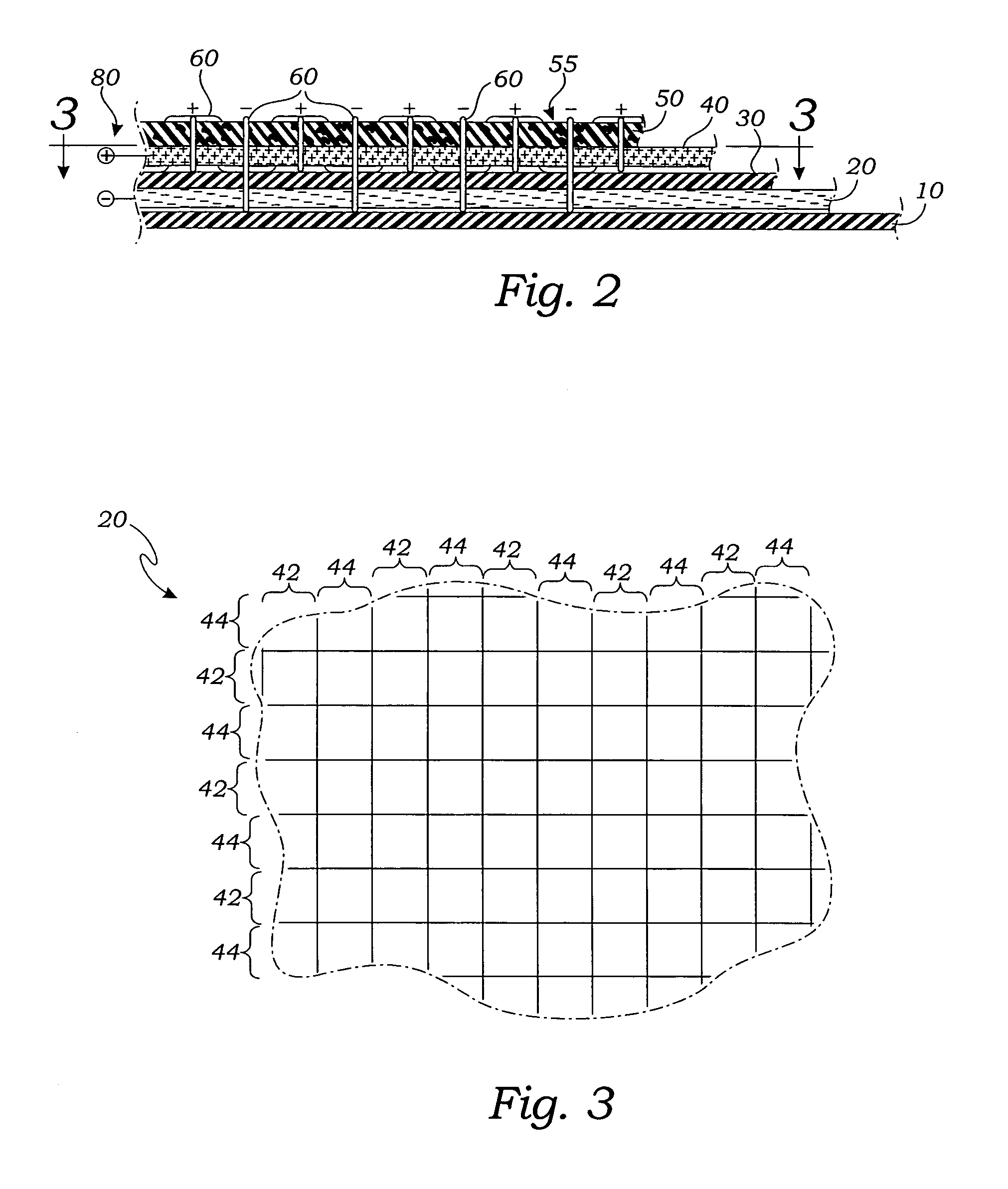
[0032]In a first embodiment, shown in cross section in FIG. 2, the invention comprises a plurality of fabric and plastic sheet layers including in sequence from a bottom to a top of the blanket apparatus, a bottom abrasion resistant layer 10 preferably of a material such as nylon or canvas, a bottom electrically active layer 20 preferably a woven fabric with all threads having an electrically conductive portion, an electrically insulating layer 30, preferably of a thin flexible plastic sheet stock such as polypropylene, a top electrically active layer 40, preferably a woven fabric with alternating electrically conductive portions 42, made up of threads 60 having a conductive metallic content; portions 42 being spaced apart by non-conductive portions 44, made up of threads 70 that have no conductive content and therefore remain electrically neutral. A typical pattern is shown in FIG. 3. A top abrasion resistant layer 50, preferably, as with layer 10, a nautical canvas or a nylon rip-...

second embodiment

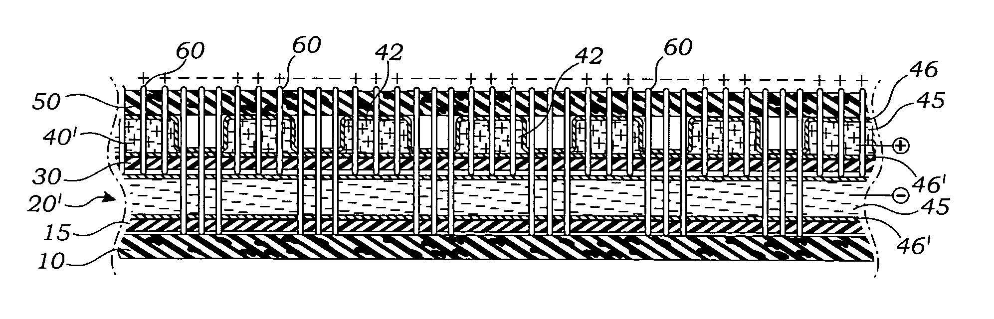
[0036]In the present invention, shown in FIGS. 4A, 4B and 5, the top electrically active layer 40′, refer here to FIG. 4A, is an electrically conductive fluid 45 held between a pair of insulating films 46, 46′, the films pressed together and bonded in places to form the pattern of non-conductive portions 44 as they are void of the conductive fluid 45, and thereby forming the pattern of conductive portions 42 interspersed by default, with the non-conductive portions 44. It is noted, that in FIG. 5, the conductive portions 42 are all in electrical common. The fluid 45 is of a type that is curable to form a flexible solid such as would be the case if the fluid 45 were a liquid curable rubber loaded with a fine metallic powder, preferably copper filings. Such a curing step is preferably ultra-violet light or by elevated temperature baking. In FIG. 4A it is seen that threads 60 are sewn through abrasion resistant top layer 50, electrically conductive portions 42 of the top electrically a...


PUM


Abstract

A flexible blanket is made of plural layers including a pair of mutually insulated electrically conductive layers. Electrically conductive stitchings extend between the electrically conductive layers, and a top abrasion resistant layer and are exposed on its exterior surface. A voltage potential is applied between the conductive layers so that the exposed stitches can provide an electric shock to an animal's foot when it is brought into contact with the exposed surface.

Description

RELATED APPLICATIONS[0001]This application is a Continuation In Part Application of a prior filed application having Ser. No. 10 / 728,505 and filing date of Dec. 5, 2003 now U.S. Pat. No. 6,817,138 and entitled: Flexible Cover Providing Electrical Shock Upon Contact.INCORPORATION BY REFERENCE[0002]Applicant(s) hereby incorporate herein by reference, any and all U.S. patents, U.S. patent applications, and other documents and printed matter cited or referred to in this application.BACKGROUND OF THE INVENTION[0003]1. Field of the Invention[0004]This invention relates generally to covers or blankets for machines, boats, cars and such, and more particularly to such a cover having a set of electrically conductive stitches on one side so that an electrical shock is received by an animal coming into contact with the cover.[0005]2. Description of Related Art[0006]The following art defines the present state of this field:[0007]Robinson, U.S. Pat. No. 3,366,854 describes an installation for rep...

Claims


Application Information

Patent Timeline
Patent Type & Authority Patents(United States)
IPC IPC(8): A01M29/00A01M29/26H05C1/06H05C3/00
CPCA01M29/26H05C1/06
Inventor MCGILL, DAVID TAYLORMCGILL, CHERYL GAY
Owner MCGILL DAVID TAYLOR
Why Eureka
Try Eureka