Paintgun with pneumatic feeding and discharging process

a technology of pneumatic feeding and discharging process, which is applied in the direction of white arms/cold weapons, lighting and heating apparatus, and combustion types, etc., can solve the problems of easy damage to the human body by projecting from the barrel, easy damage to the human body, and high safety threat, so as to achieve the effect of ensuring use safety and reducing malfunction

Inactive Publication Date: 2005-08-09
SHENG CHIH SHENG
View PDF16 Cites 77 Cited by
  • Summary
  • Abstract
  • Description
  • Claims
  • Application Information

AI Technical Summary

Benefits of technology

[0010]It is a primary object of the invention to provide a paintgun with pneumatic feeding and discharging process in which the paintball discharge is pneumatically controlled to replace the conventional mechanical way by engaging the firing hammer. Thus, the use safety is much ensured and the malfunction thereof is considerably reduced.
[0011]It is another object of the invention to provide a paintgun with pneumatic feeding and discharging process which has advantages of simple configuration, easy assembly and low cost.
[0012]It is a further object of the invention to provide a paintgun with pneumatic feeding and discharging process in which a limited amount of airflow is used to push a push tube forward first such that the paintball is brought forward to change the pressure of the front and rear ends of the flow-guiding valve. Accordingly, a great amount of airflow is brought through a major air channel for discharging the paintball. Thus, the invention has advantages of smooth feeding of air flow. In addition, the paintball can be discharged by thrust of air flow even with smaller air pressure.

Problems solved by technology

The safety is much threatened.
Moreover, the components of the conventional paintgun are numerous, and the connection thereof is complicated so that it's not easy for assembly and malfunction.
During the discharge, it moves to and fro such that the rear member 194 projecting from the barrel easily injure the human body.
It's much dangerous.
Therefore, the reduced air pressure can't bring the paintball B forward for discharge.
However, the higher the air pressure of the tank is, the more the cost thereof will be raised.
Besides, the available air amount is also diminished and the danger is much elevated.

Method used


Image

  • Paintgun with pneumatic feeding and discharging process
  • Paintgun with pneumatic feeding and discharging process
  • Paintgun with pneumatic feeding and discharging process

Examples


Embodiment Construction

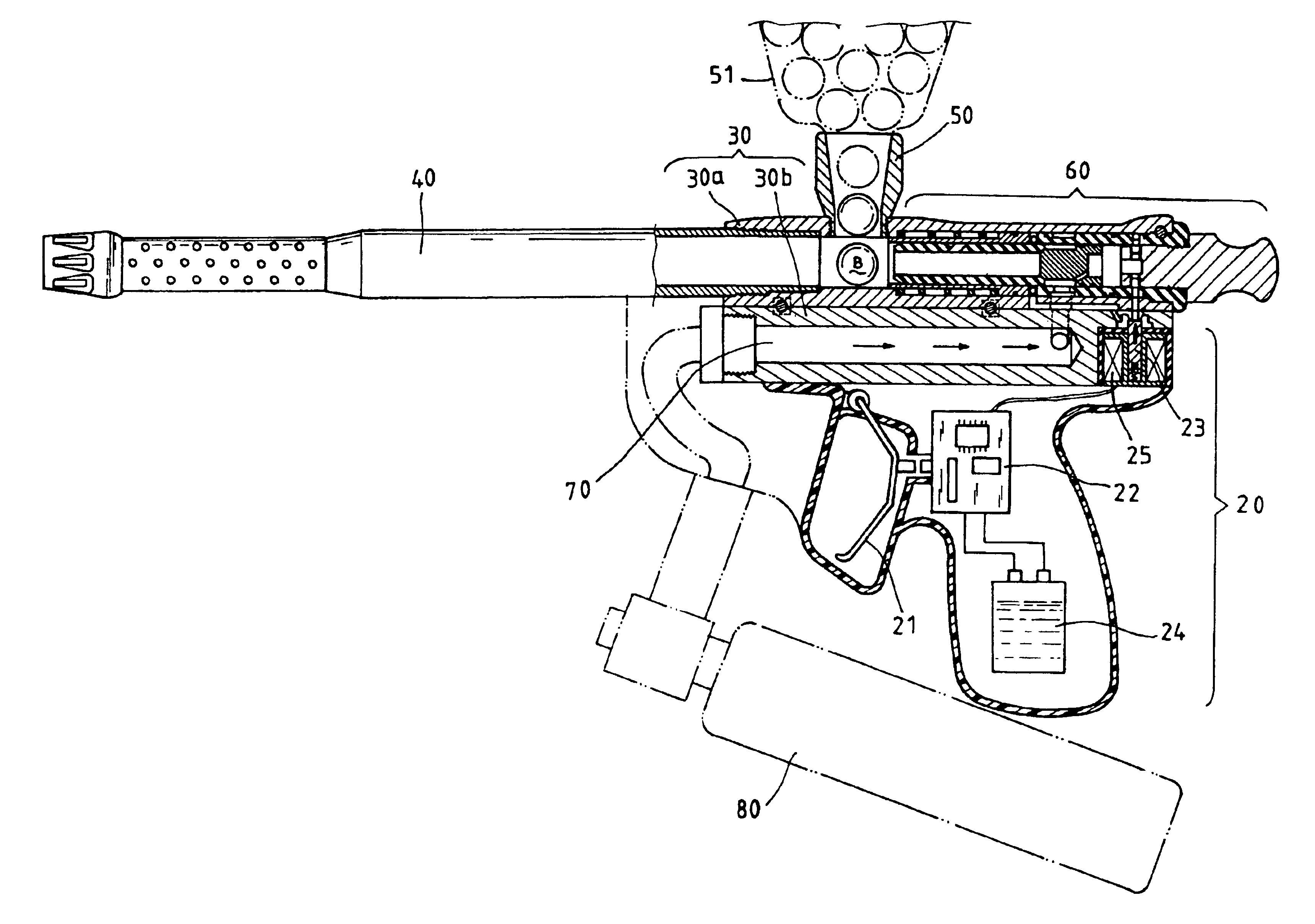
[0032]First of all, referring to FIG. 5, an improvement of the paintgun of the invention is shown. The paintgun in accordance with the invention mainly includes a trigger assembly 20, a barrel assembly 30 and a pneumatic delivery mechanism 60.

[0033]The trigger assembly 20 is used to actuate the firing element of paintballs B.

[0034]The barrel assembly 30 is fitted above the trigger assembly 20. Besides, the barrel assembly 30 can be formed in one piece or composed of an upper and a lower barrel 30a, 30b, as shown in FIG. 5(a), and both of which are assembled, as shown in FIG. 5(b), by fastening elements 32 such as screws or the like. Furthermore, the length of the lower barrel 30b is adjustable to different applications and not required to correspond to that of the upper barrel 30a. A bore 40 is provided at the front end thereof. Besides, a paintball-feeding tube 50 is disposed above the bore 40 for connecting with a tank 51 to supply paintballs B.

[0035]The pneumatic delivery mechani...


PUM


Abstract

The invention relates to a paintgun with pneumatic feeding and discharging process characterized by a pneumatic delivery mechanism. The pneumatic delivery mechanism comprises a flow-guiding body forming a major air channel at front end and a flow-guiding chamber at rear end thereof, a flow-guiding movable body utilizing a valve body to divide the flow-guiding chamber into a front and a rear air pressure chamber with different pressure area and a delivery tube placed around a tube at front part of the flow-guiding body. Moreover, a stopper controls the opening or closing of air flow channel, thereby changing the pressure difference between the front and the rear air pressure chambers. The delivery tube is shifted forward by a small amount of air flow fed into a minor air channel for pushing a paintball a little forward. Thereafter, the paintball is discharged by thrust of air flow into the major air channel.

Description

BACK GROUND OF THE INVENTION[0001]1. Field of the Invention[0002]The invention relates to a paintgun with pneumatic feeding and discharging process, and more particularly, to a paintgun which controls the opening and closing of the airflow channel in such a way that the flow-field pressure is changed to complete two-stage feeding and discharging process.[0003]2. Description of the Related Art[0004]A plurality of conventional paintguns (e.g. TW 447697, 443486, 406894, 437941, etc.), as shown in FIGS. 1 and 2, have a trigger assembly 11 above which a barrel assembly 12 is disposed. The barrel assembly 12 consists of an ejector tube 121 and an air chamber tube 122 both of which are in parallel with each other. A bore 13 is installed at the front end of the ejector tube 121 while a feeding tube 14 is fixed at the top thereof. The feeding tube 14 is connected with a loader to supply paintballs B. The air chamber tube 122 is fitted with an air valve 161 and an air valve spring 162 at the ...

Claims


Application Information

Patent Timeline
Patent Type & Authority Patents(United States)
IPC IPC(8): F41B11/00F41B11/32F41B11/02
CPCF41B11/52F41B11/57F41B11/723
Inventor SHENG, CHIH-SHENG
Owner SHENG CHIH SHENG
Why Eureka
Try Eureka