Helicopter with two or more rotor heads

a rotor head and helicopter technology, applied in the direction of rotorcraft, aircraft components, aircrafts, etc., can solve the problems of limiting the size of the rotor to be used, the use of two or three rotors does not improve matters, and the craft cannot be stabilized, so as to achieve the effect of improving efficiency and further efficiency

Inactive Publication Date: 2012-09-27
WILKE PAUL
View PDF9 Cites 40 Cited by
  • Summary
  • Abstract
  • Description
  • Claims
  • Application Information

AI Technical Summary

Benefits of technology

[0013]Further efficiency is gained since this invention does not require a tail rotor, as conventional helicopters do.
[0014]Another source of improved efficiency is that with conventional helicopters, the fuselage can only be mounted in the down wash of the rotor. The down force this creates has to be overcome by generating more lift. With the present invention, the fuselage can be mounted in between the rotors, thereby keeping it out of the down wash.

Problems solved by technology

The use of two or three rotors does not improve matters, since in case of failure of one, the craft can still not be stabilized.
The latter solution limits the size of the rotor to be used, because in larger rotor sizes, the momentum is such that rapid control movements cannot be adequately translated into the desired rotational speed.
One disadvantage of this set-up is that in forward flight, the aircraft is tilted against the direction of motion, generating drag.
It also limits the use as a stabilized platform, e.g. to mount a camera on.
The main disadvantages of these solution are mechanical complexity, stability issues when rotors are tilted, and drag in forward motion.
Disadvantages are either aerodynamically as in the case of Wobben, or limitations in maneuverability as in the case of Madet, since the force in the horizontal plane can only be exercised in one direction.
In the case of two rotor heads, the configuration is limited to concentric mounting of the rotors.

Method used


Image

  • Helicopter with two or more rotor heads
  • Helicopter with two or more rotor heads
  • Helicopter with two or more rotor heads

Examples


Embodiment Construction

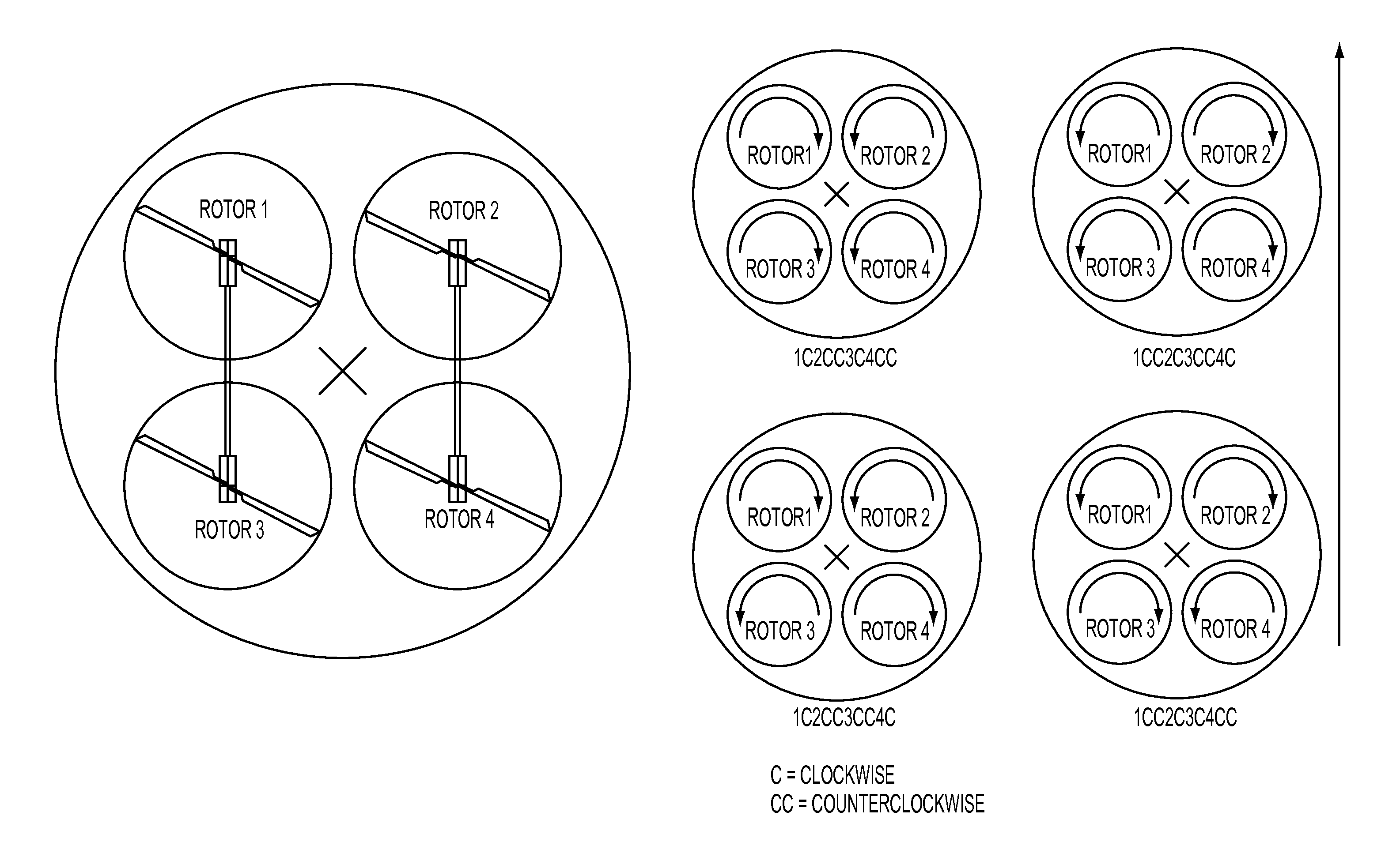
[0025]The present invention gains an additional degree of freedom by using aerodynamic drag differences in each rotor blade as they go through a 360 degrees rotation, and the combination of these forces generated by two or more rotor blades according to a novel scheme. In the embodiment here described, there are four rotor heads, but in an analogous way the same applies to embodiments with smaller or larger numbers of rotors, an example of which is given.

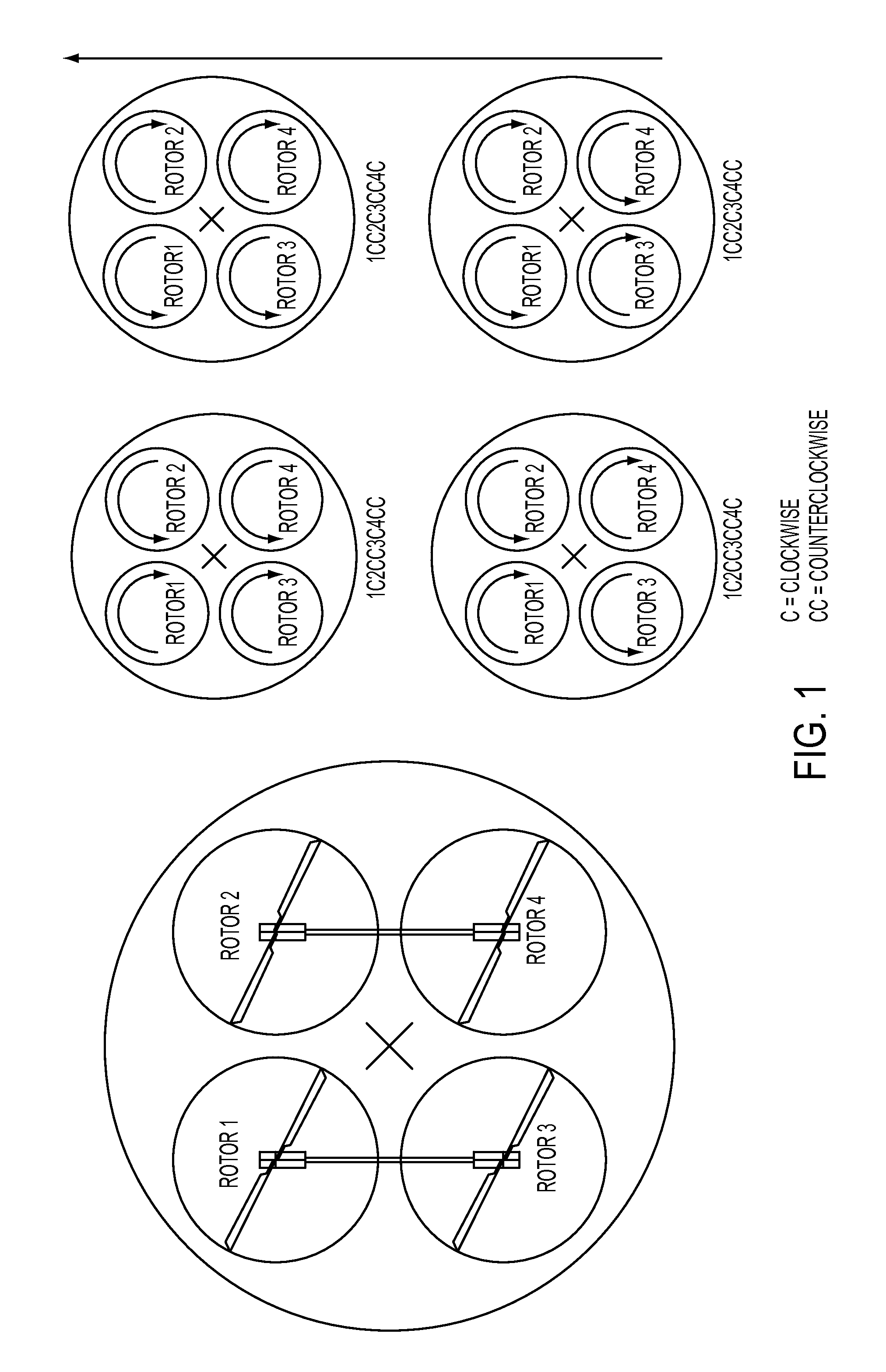
[0026]FIG. 1 explains the different possibilities that exist for the rotation of each of the rotors with respect to the main direction of movement in the case of four rotors. In order to name these different set-ups, the numerals 1 . . . 4 stand for the rotor head number, C for clockwise rotation and CC for counter-clockwise rotation. Thus, the designation 1C2CC3C4CC describes essentially similar rotor movement as does the designation 1CC2C3CC4C, the principal difference being the main direction of movement. The same relative relati...


PUM


Abstract

A helicopter with two or more rotor heads with full swash plate control and a novel control scheme to allow for propulsion in the horizontal plane in all directions, allowing the aircraft to fly in all directions in a truly horizontal fashion. Furthermore, a manual input device to control the additional control freedoms thus gained, and an electronic control system that combines manual inputs with inputs from sensors and translates these inputs into directions for the actuators of the two or more swash plates in order to control the aircraft, taking into account the novel control scheme.

Description

CROSS REFERENCE TO RELATED APPLICATIONS[0001]This application claims the benefit of Provisional U.S. Patent Application No. 61 / 365,779, filed Jul. 20, 2010, the entirety of which is incorporated herein by reference.BACKGROUND OF THE INVENTION[0002]The vast majority of helicopters presently in use is of the single rotor type, which type, as was already noted by Beckwith in U.S. Pat. No. 3,002,712, suffers from the requirement of one-hundred percent reliability of each of the parts in order to be considered safe enough for manned flight. The only exception to this rule is that with some kinds of incidents such as engine failure, a helicopter may be saved by storing energy in the rotor blades during descend, to be released shortly before landing to slow down the aircraft. This is called autorotation, and in order to work effectively, it requires the rotor blades to be sufficiently heavy to accumulate the required amount of energy. The use of two or three rotors does not improve matters...

Claims


Application Information

Patent Timeline
Patent Type & Authority Applications(United States)
IPC IPC(8): B64C27/08B64C27/57
CPCB64C27/08
Inventor WILKE, PAUL
Owner WILKE PAUL
Why Eureka
Try Eureka