Automatic air release system with shutoff valve

a technology of automatic air release and shutoff valve, which is applied in the direction of functional valve types, water supply installation, transportation and packaging, etc., can solve the problems of affecting the maintenance efficiency of the air release valve, and requiring additional labor. , to achieve the effect of preventing damage from a leaking air release valve, preventing damage, and facilitating rapid maintenan

Active Publication Date: 2005-08-09
NAT CITY BANK CO
View PDF3 Cites 26 Cited by
  • Summary
  • Abstract
  • Description
  • Claims
  • Application Information

AI Technical Summary

Benefits of technology

[0017]Embodiments of the invention include the use of an apparatus as described above in a method for preventing fluid leakage from a failed air release valve on a fluid-filled plumbing system. Upon the failure of the air release valve an amount of fluid from the plumbing system will escape past the air release valve. In an embodiment, when such an apparatus as is described above is coupled to a fluid-filled plumbing system at such a failed air release valve, if the rate of leaking fluid is sufficiently high, the fluid will accumulate in the container triggering the liquid sensitive switch, which switch action leads to the closing of the liquid sensitive valve. Because the liquid sensitive valve is a component of the constrained path, when the liquid sensitive valve closes fluid flow through said constrained path is stopped. Thus, in an embodiment the apparatus effects the prevention of fluid leakage from an air release valve after some amount of fluid has passed through the failed air release valve.
[0019]Another embodiment of the invention provides for a method for signaling the failure of an air release valve on a fluid-filled plumbing system. Such signaling may also enable the prevention of leakage from the failed air release valve such as where the signal induces rapid maintenance on the fluid-filled plumbing system. In such an embodiment an apparatus may be used that includes an air release valve coupled to a fluid-filled plumbing system, a constrained path coupled to said air release valve through which fluid may flow from the air release valve into a container, a container coupled to said fluid-filled plumbing system for containing fluid flow that passes from said air release valve through said constrained path, and a liquid sensitive switch within said container. As described above, when the air release valve fails fluid may accumulate in the container triggering the liquid sensitive switch. The triggering of the liquid sensitive switch may lead to a signal, which is an indication of the failure of the air release valve. Such a signal may use any method of signaling such as a visual signal, electrical signal, or an auditory signal.
[0020]Because of a recognized potential for a leak from a fluid-filled plumbing system to cause damage to objects and persons in the vicinity of the leak, an embodiment of the invention provides a method for preventing damage resulting from a failed air release valve on a fluid-filled plumbing system. Quite simply, damage from a leaking air release valve can be prevented by accumulating the leaking fluid in a container. A further method of preventing damage is to provide a liquid sensitive valve connected to the air release valve via a constrained path, which liquid sensitive valve is closed upon leakage from the air release valve.

Problems solved by technology

The limited use of air release valves in fire sprinkler and standpipe systems has been primarily within fire pump housings where the removal of trapped air is critical to prevent cavitation of the pump impeller.
There are problems associated with the use of either manual or automatic air release valves generally throughout a fire sprinkler or standpipe system to remove air therefrom.
One problem with the use of manual valves in such a fire sprinkler or standpipe system is that their use would require additional labor during the filling process, and would require retained knowledge of the system so persons could be directed to each and every such manual air release valve.
A problem with the use of automatic air release valves in fire sprinkler and standpipe systems is that, because no person would be present tending the air release, any inherent liquid release during normal operation of the valve would be discharged to the interior of the building in the area of the valve.
Such a discharge can damage or destroy parts of the building (such as drywall or ceiling tiles), infrastructure in the building (such as power or computer cabling), or can damage objects within the building (such as merchandise, computers, fixtures, furniture, etc.).
The problem of property damage is particularly weighty when considering the possibility of eventual failure of the valve, which would allow discharge of greater amounts of liquid.
In order to prevent such damage would require the automatic air release valve to be hard-piped to a drain, which because of the requirements for the location of these valves becomes cost prohibitive, impractical, or virtually impossible to hard pipe these devices to a drain.

Method used


Image

  • Automatic air release system with shutoff valve
  • Automatic air release system with shutoff valve
  • Automatic air release system with shutoff valve

Examples


Embodiment Construction

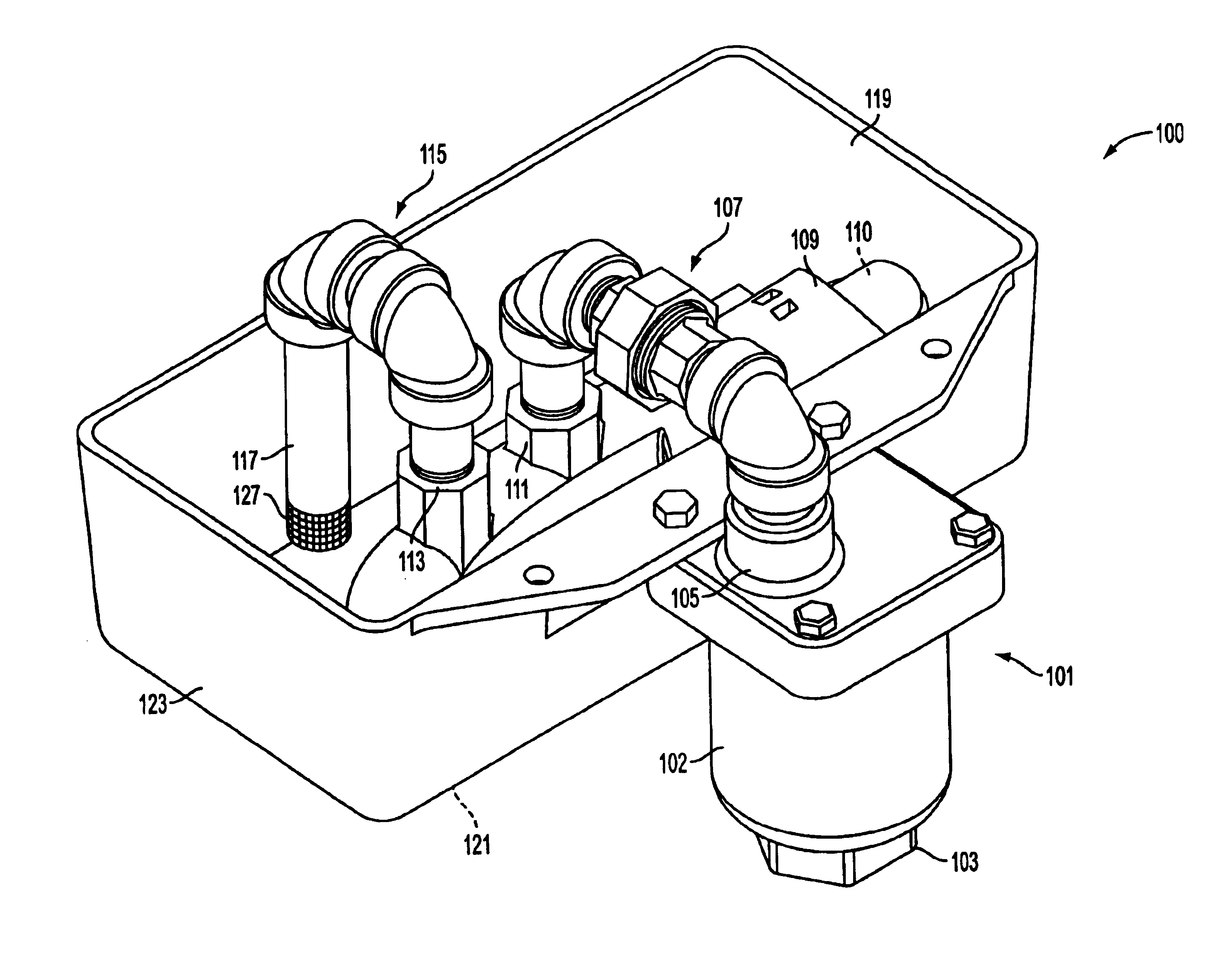
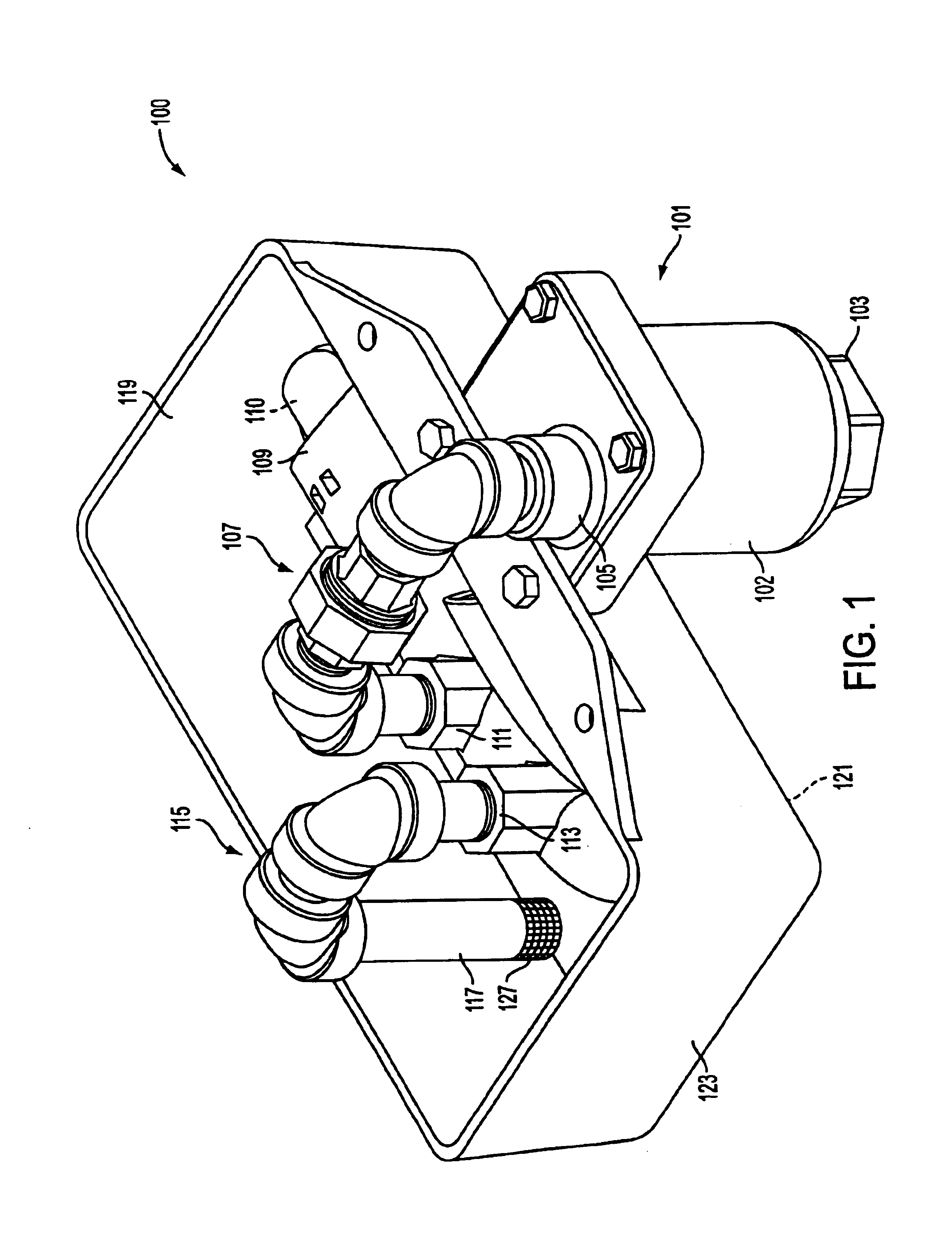
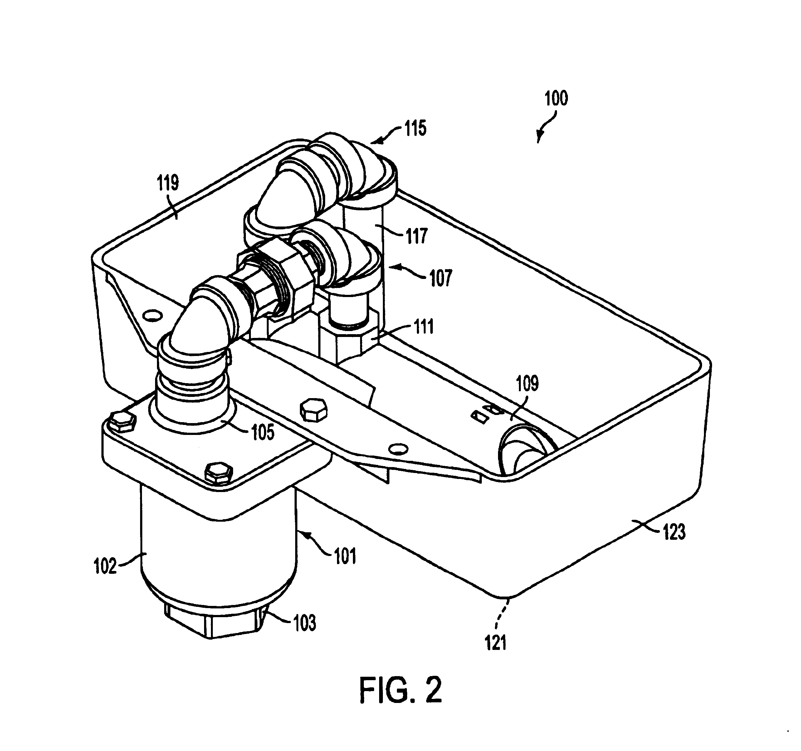
[0026]FIGS. 1 through 5 provide for an embodiment of a system (100) to prevent a failed air release valve (101) from leaking until it can be replaced. Such a system (100) can notify a manufacturer, building supervisor, or other party that the air release valve (101) has failed and needs to be replaced.

[0027]As seen in FIG. 1, the system (100) includes an air release valve (101), which may be any type of air release valve regardless of mechanism but will generally be a float-and-chamber based release valve such as those discussed above. The air release valve (101) is attached via a coupler (103) to a pipe (not shown) which is part of a plumbing system (not shown), such as a fire sprinkler or standpipe system. While discussed mainly in relation to a fire sprinkler or standpipe system, embodiments of the invention may be useful on any fluid-filled plumbing system that comprises an air release valve (such as air release valve (101)), including a hot water, radiating heat system, or othe...


PUM


Abstract

Systems and methods are provided that allow for the continued operation of a fire sprinkler or standpipe system after the failure of an air release valve, wherein connected to the air release valve is a system that collects and contains fire extinguishing liquid leaked from an air release valve, as well as being able to detect and stop such leaks that could not be contained by the system.

Description

CROSS-REFERENCE TO RELATED APPLICATIONS[0001]This application claims the benefit of U.S. Provisional Application No. 60 / 443,796, filed Jan. 30, 2003.BACKGROUND OF THE INVENTION[0002]1. Field of Invention[0003]This apparatus relates to the automatic removal of air from sprinkler and standpipe systems without having to hard pipe discharge liquid to a drain.[0004]2. Description of Related Art[0005]To fight fires in modern office buildings, firefighters use a wide variety of tools but are also regularly aided by systems (fire sprinkler and standpipe systems) within the building itself. Modern buildings almost universally include fire sprinkler systems to contain or extinguish fires in the building without human intervention. Modern buildings that have large foot prints or are three stories or more in height are also provided with standpipe systems for manual intervention by either occupants or firefighters.[0006]Fire sprinkler systems generally follow a fairly standardized principle. A ...

Claims


Application Information

Patent Timeline
Patent Type & Authority Patents(United States)
IPC IPC(8): F17D5/00F17D5/02
CPCF17D5/02Y10T137/0324Y10T137/309Y10T137/3099A62C35/68
Inventor CABRAL, MICHAEL F.KIRN, MICHAEL D.
Owner NAT CITY BANK CO
Why Eureka
Try Eureka