
Projector attachment for ellipsoidal lamp

a technology of ellipsoidal lamps and projectors, which is applied in the direction of fixed installation, lighting and heating equipment, instruments, etc., can solve the problems of limited projection patterns of modern stage projectors, inconvenient mounting, and large equipment costs of projectors

Active Publication Date: 2005-08-09
GAMPRODS
View PDF4 Cites 16 Cited by
  • Summary
  • Abstract
  • Description
  • Claims
  • Application Information

AI Technical Summary

Benefits of technology

[0018]A process and apparatus reversibly converts an ellipsoidal stage lamp into a projector for projecting light with special effects onto a stage. The ellipsoidal stage lamp has a base with a lamp having a filament; an ellipsoidal reflector mounted to the base, with the filament of the lamp at the focus of the ellipsoidal reflector; a shutter section for containing shutters to impart borders to a projected beam from the stage lamp; a barrel mounted to the shutter section; and a lens tube having projecting lenses for slidable mounting within the barrel, for projecting and focusing a projected beam from the ellipsoidal stage lamp. The apparatus includes a replacement for the shutter section, which is a cabinet for disposition within the ellipsoidal stage lamp to replace the shutter section. The cabinet defines a first opening disposed along and around the optical axis of the ellipsoidal stage lamp and wh...

Problems solved by technology

Simply stated, patterns projected by modern stage projectors are limited only by the imagination of the lighting designer.
Because of their mechanical complication, projectors are usually large expensive instruments.
Their mounting is far from simple.
Again, because of size and mechanical complication, special mounting of the resulting instrument is required.
Further, the altered ellipsoidal theatrical lamp can never be recovered for conventional use.
While this instrument is useful in certain situations, the narrow confines of the iris slot give this instrument-restricted applicability.

Method used


Image

  • Projector attachment for ellipsoidal lamp
  • Projector attachment for ellipsoidal lamp
  • Projector attachment for ellipsoidal lamp

Examples


Embodiment Construction

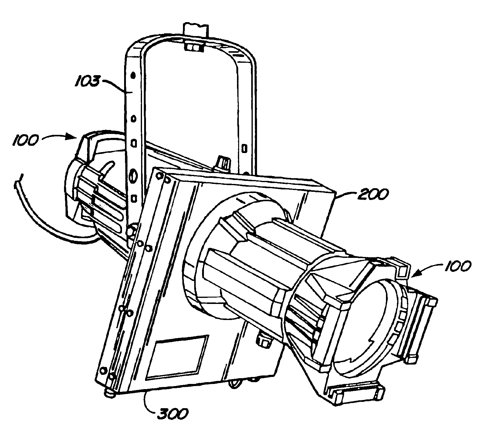
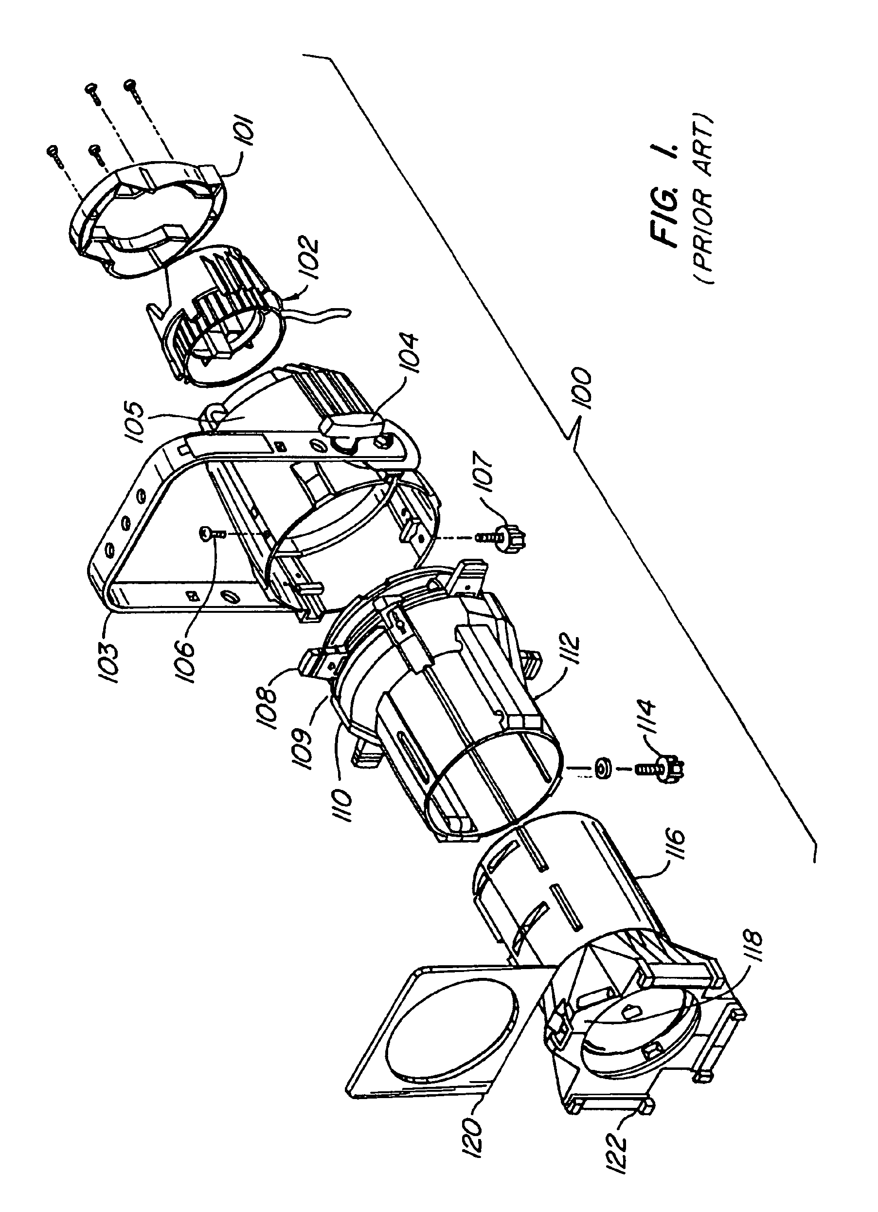
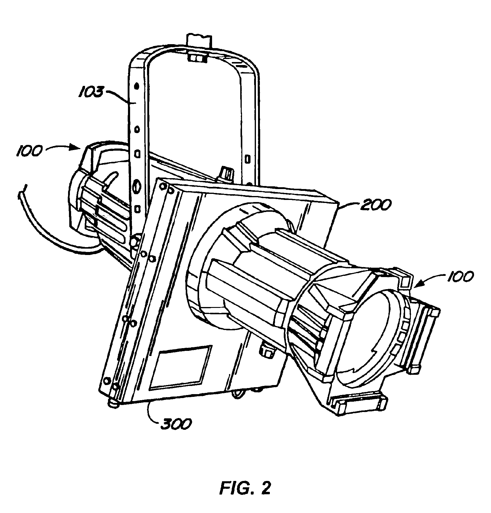
[0025]Referring to FIG. 1, an exploded view of ellipsoidal stage lamp 100 of the prior art is shown. Base-mounting yoke 103 has lamp base and ellipsoidal reflector 102 and lamp handle 101 mounted and locked into position by yoke locking knob 104. As discussed below, cabinet 200 is mounted to this portion of the lamp for the reversible conversion of ellipsoidal stage lamp 100 into a projector.

[0026]Shutter assembly-retaining bolts 106 and barrel rotation knob 107 hold shutters 108 to reflector housing 105. The shutter assembly contains pattern-holding slot 109 and includes drop-in iris 110. When the shutter assembly is temporarily removed, and cabinet 200 inserted to the lamp, reversible conversion to a projector can occur.

[0027]Base-mounting bayonet fitting 111 (hidden from view, see FIG. 3) is coupled to barrel 112. Barrel 112 mounts beam focus knob 114. Finally, lens tube 116, containing projecting lenses telescopes within barrel 112, is adjusted in such telescoping relation by be...


PUM


Abstract

A process and apparatus reversibly converts an ellipsoidal stage lamp into a projector for projecting light with special effects onto a stage. The apparatus includes a replacement for the shutter section, which is a cabinet for disposition within the ellipsoidal stage lamp to replace the shutter section. The cabinet defines a first opening disposed along and around the optical axis of the ellipsoidal stage lamp and which is open to the base and lamp having a filament. The cabinet has one open side for permitting the sliding insertion of a drawer. The drawer, which is mountable to the cabinet, has a second opening disposed along and around the optical axis of the ellipsoidal stage lamp and open to the base and lamp when the drawer is inserted to the cabinet. A movable projector plane is mounted to the drawer across the second opening for insertion to the cabinet at the open side.

Description

CROSS-REFERENCES TO RELATED APPLICATIONS[0001]This application claims priority from U.S. Provisional Application Ser. No. 60 / 407,606 filed Aug. 29, 2002.STATEMENT AS TO RIGHTS TO INVENTIONS MADE UNDER FEDERALLY SPONSORED RESEARCH OR DEVELOPMENT[0002]Not ApplicableREFERENCE TO A “SEQUENCE LISTING,” A TABLE, OR A COMPUTER PROGRAM LISTING APPENDIX SUBMITTED ON A COMPACT DISK[0003]Not Applicable[0004]This invention relates to projectors used on stages to project special lighting effects such as fire, rain, and snow. More particularly, a special effects projector attachment is disclosed for attachment to a conventional ellipsoidal stage lamp to enable rapid projector insertion into lighting arrays such as rows and columns of lamps on theatrical lighting trees.BACKGROUND OF THE INVENTION[0005]The most useful stage lamp for use in theatrical and related lighting is the ellipsoidal lamp. As is well known, an ellipse has two foci. Once such an ellipse is rotated 180°, the boundaries of the e...

Claims


Application Information

Patent Timeline
IPC IPC(8): G03B21/00
CPCG03B21/00G03B21/001
Inventor TAWIL, JOSEPHCONLON, LEE
Owner GAMPRODS
Learn More