Electrical wiring device with multiple types of wire terminations

Inactive Publication Date: 2005-08-09
LEVITON MFG
View PDF9 Cites 17 Cited by
  • Summary
  • Abstract
  • Description
  • Claims
  • Application Information

AI Technical Summary

Benefits of technology

[0006]The instant invention provides a wiring device which provides all three of the above-described electrical conductor to wiring device wiring techniques. The wiring device has a number of contact pads, one for each contact of the wiring device. The surface of the contact pad is scored to permit it to better grip the bared end of an electrical conductor. A threaded aperture in the contact pad threadingly engages a threaded terminal screw. The bared end of an electrical conductor can be bent into a u-shape and placed about the threaded portion of the terminal screw and is engaged by the backside of the terminal screw head and front surface of a clamping plate. The u-shaped conductor can be closed into a circular shape before the terminal

Problems solved by technology

Although one or two of these approaches are present in a single wiring device there is not

Method used


Image

  • Electrical wiring device with multiple types of wire terminations
  • Electrical wiring device with multiple types of wire terminations
  • Electrical wiring device with multiple types of wire terminations

Examples


Embodiment Construction

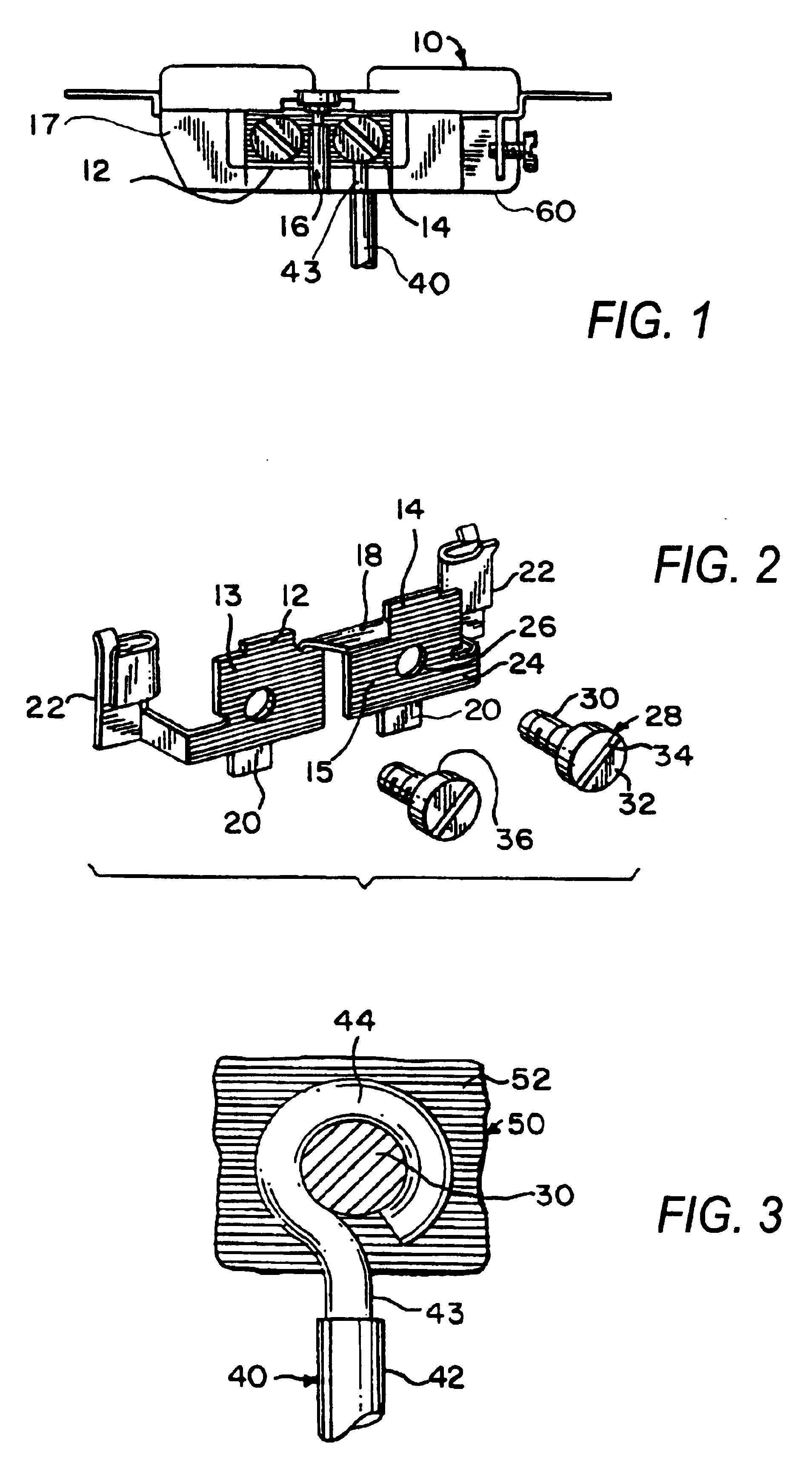
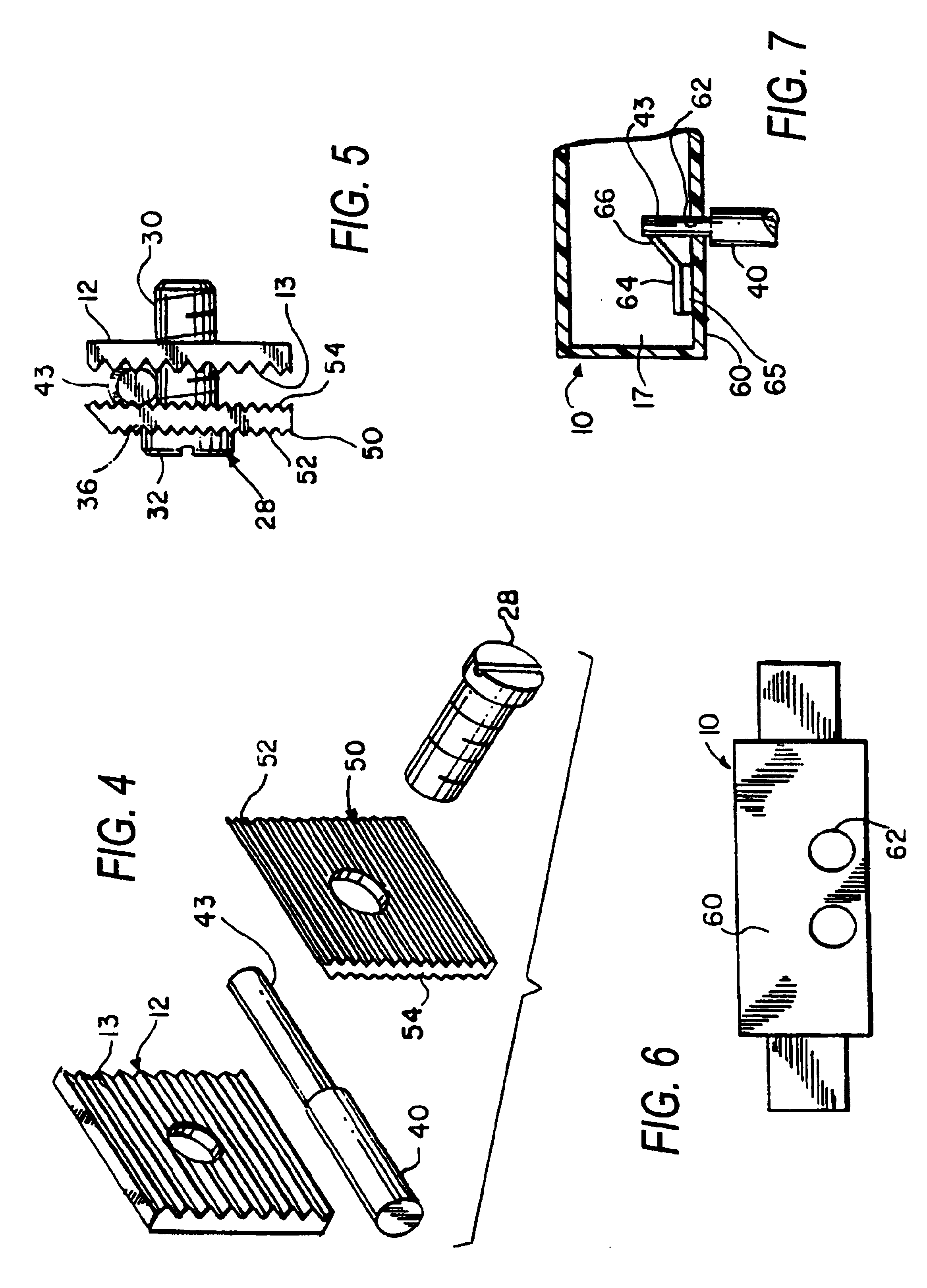
[0019]Turning to FIGS. 1 and 2 there is shown a wiring device 10 which may be a receptacle, switch or the like. The wiring device 10 includes a body 17 having a bottom surface 60 with aperture 62 therethrough, as shown in FIGS. 6 and 7. Two contact pads 12 and 14 which fit in a recess within the side of the body of wiring device 10 are exposed to receive a bared end 43 of a conductor 40. A barrier 16 of insulating material is positioned so that the barrier 16 separates the contact pads 12 and 14 and is employed when the contact pads 12 and 14 are separately wired. A bridge 18 of metal joins the contact pads 12 and 14 if the circuits are wired in common, and may be removed when the circuits are to be separately wired. Tabs 20 and side wings 22 are employed as anchor elements to anchor the contact pads 12 and 14 in place in the body 17 of the wiring device 10. Each of front faces 13 and 15 , respectively, of the contact pads 12 and 14 are serrated as at 24 to better grip a conductor p...


PUM


Abstract

A wiring device is provided with three different ways in which the bared end of an electrical conductor can be coupled to the contacts inside the body of a wiring device. A clamping plate is placed upon the threaded body of a terminal screw. In a first arrangement the bared end is formed about the terminal screw and trapped between the head of the terminal screw and a first surface of the clamping plate which forces the conductor into firm contact with the first surface of the clamping plate. In another arrangement the straight bared end of the conductor is trapped between a second surface of the clamping plate and a contact plate. The movement of the conductor and clamping plate is controlled by the terminal screw. Apertures are placed in the bottom of the device housing adjacement the contacts in the housing. A contact arm, formed as a one-way clutch grips the straight bared end of a conductor to make contact with the contacts of the device but prevents withdrawal of the conductor.

Description

[0001]This application is a continuation of application Ser. No. 09 / 426,458, filed Oct. 25, 1999, now abandoned.BACKGROUND OF THE INVENTION[0002]1. Field of the Invention[0003]The instant invention is directed to the field of wiring devices and more particularly to wiring devices having multiple means to connect electrical conductors to such wiring devices.[0004]2. Description of the Prior Art[0005]Prior art devices have terminal screws which permit the bared end of an electrical conductor to be placed under the head of such terminal screw or push-in sections which allow the bared end of an electrical conductor to be inserted therein or a combination of a terminal screw and clamping plate which traps the bared end of an electrical conductor between a clamping plate and a contact pad of a wiring device. Although one or two of these approaches are present in a single wiring device there is not a single wiring device which offer all three conductor to wiring device clamping techniques....

Claims


Application Information

Patent Timeline
IPC IPC(8): H01R11/00H01R11/05H01R4/36H01R4/28
CPCH01R11/05H01R4/363
Inventor POH, PATRICKLOPEZ, JUAN M.
Owner LEVITON MFG
Why Eureka
Try Eureka