Insulated transition spool apparatus

Active Publication Date: 2005-08-09
CHEVROU USA INC
View PDF19 Cites 41 Cited by
  • Summary
  • Abstract
  • Description
  • Claims
  • Application Information

AI Technical Summary

Benefits of technology

[0008]The present invention is directed to an insulated transition spool, which allows for pressure-tight attachment of unheading devices or other types of devices to vessels, such as coker vessels, when it is important to maintain pressure-tight seals through many operational cycles. In the pressure vessels used in delayed coking, operating temperatures cycle between low to high temperatures in a short period of time. Typical coking and decoking

Problems solved by technology

These cyclic variations in temperature and static load pressures typically necessitate

Method used


Image

  • Insulated transition spool apparatus
  • Insulated transition spool apparatus
  • Insulated transition spool apparatus

Examples


Embodiment Construction

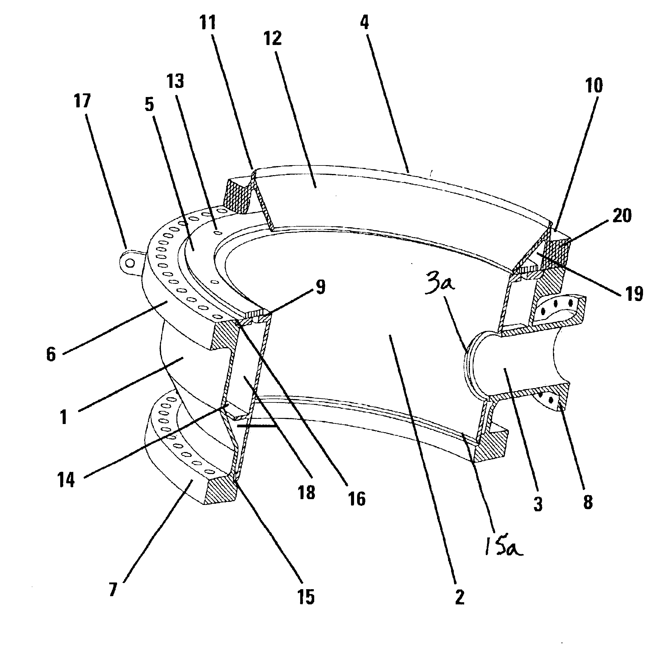
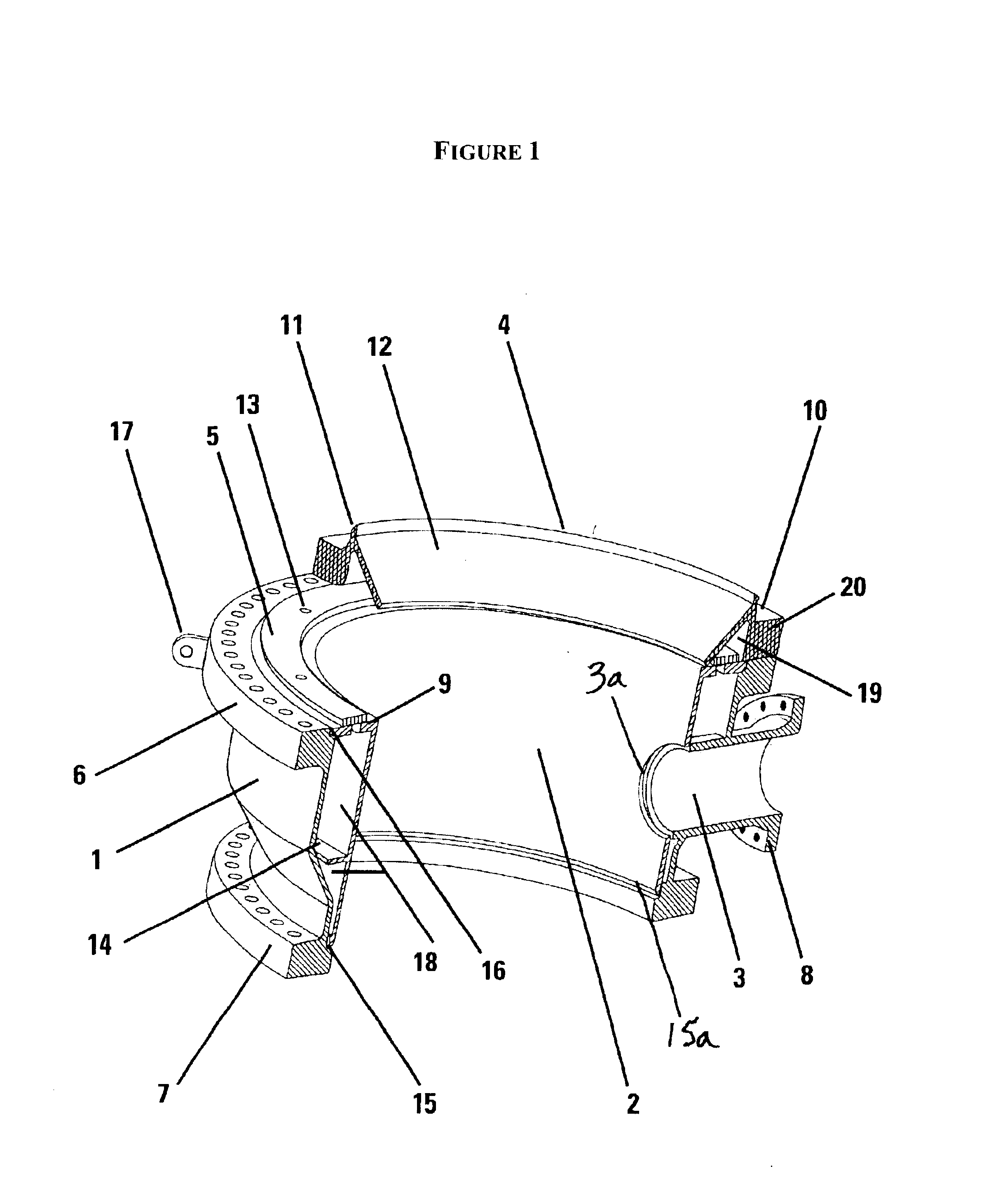
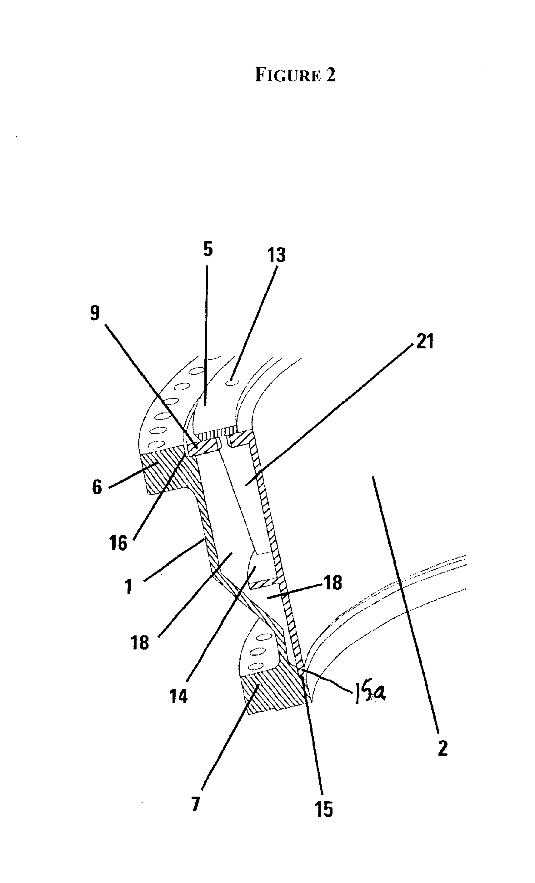
[0016]As shown in FIG. 1, the insulated transition spool comprises three major elements: (1) an outer housing 1 having a central bore along a vertical axis, a first flanged end 6, a second flanged end 7 and a first lateral aperture 3; a first registration area 15, a second registration area 16; (2) an inner housing 2, which is a straight walled “barrel” component having a central bore, a registration flange 9, a registration end 15a and a second lateral aperture 3a; and (3) a spool adapter flange 4 comprising and outer flange 20, and inner surface 12 and a support ring 5 having a plurality of vent holes 13 therein and enclosing a thermal barrier 19. These three elements are joined together such that the inner housing 2 is movably seated within the central bore of the outer housing 1 by contacting the registration flange 9 with the second registration area 16 and the registration end 15a with the first registration area to enclose a thermal barrier or insulating space 18; the first l...


PUM

PropertyMeasurementUnit
Angleaaaaaaaaaa
Angleaaaaaaaaaa
Angleaaaaaaaaaa

Abstract

An insulated transition spool apparatus for mounting unheading devices to pressure vessels, such as coker vessels, and enabling repetitive operation thereof is disclosed. The apparatus comprises an outer housing, an inner housing that encloses an insulating space between the inner and outer housing, a side feed entry aperture in each housing and a spool adapter flange to facilitate attachment of the spool to the vessel.

Description

FIELD OF THE INVENTION[0001]This invention relates to the field of pressure vessels, such as pressure vessels used in heavy hydrocarbon coking processes, and apparatus for joining vessel components.BACKGROUND OF THE INVENTION[0002]Pressure vessel innovation, especially in the petroleum refining industry, is driven by the factors of utility, safety, reliability, costs and ease of operation and maintenance. This is especially true in the petroleum refining process of delayed coking in which large pressure vessels are employed to recover valuable products by thermally cracking heavy residual hydrocarbons. Heavy residual hydrocarbon, or resid, is the recovered bottom stream from the initial refining of crude oil or other oil sources such as shale oil, coal oil, or Fischer Tropsch synthetic oil.[0003]Generally, the delayed coking process involves heating the heavy hydrocarbon feed from a fractionation unit, and then pumping the heated heavy feed into a large steel pressure vessel commonl...

Claims


Application Information

Patent Timeline
IPC IPC(8): B01B1/00C10B1/00C10B1/04C10B25/10C10B25/00
CPCB01B1/00C10B1/04C10B25/10
Inventor BOSI, DAVID M.REEVES, DAVID W.
Owner CHEVROU USA INC
Why Eureka
Try Eureka