Magnetic device having a springable winding

a technology of springs and windings, which is applied in the direction of transformers/inductance details, inductances with magnetic cores, and magnetic devices, etc., can solve the problems of increased thickness of magnetic devices, increased winding losses, and increased inductor footprints

Inactive Publication Date: 2005-08-09
ABB POWER ELECTRONICS INC
View PDF2 Cites 33 Cited by
  • Summary
  • Abstract
  • Description
  • Claims
  • Application Information

AI Technical Summary

Problems solved by technology

As winding layers are added to achieve the desired inductance or transformer ratio, the magnetic device increases in thickness and as a result the inductor footprint requires additional printed circuit board space.
Such configurations invariably lead to high

Method used


Image

  • Magnetic device having a springable winding
  • Magnetic device having a springable winding
  • Magnetic device having a springable winding

Examples


Embodiment Construction

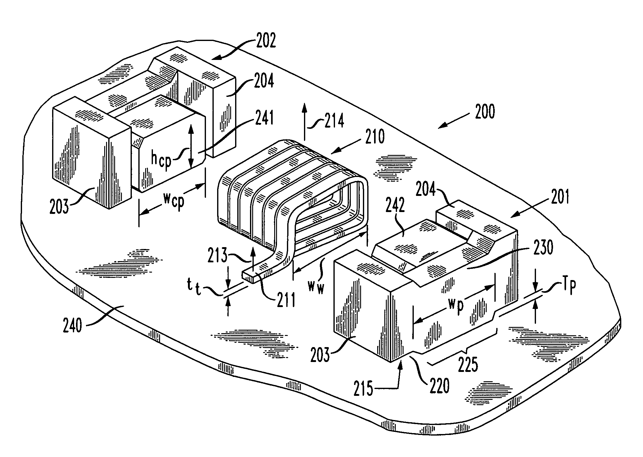
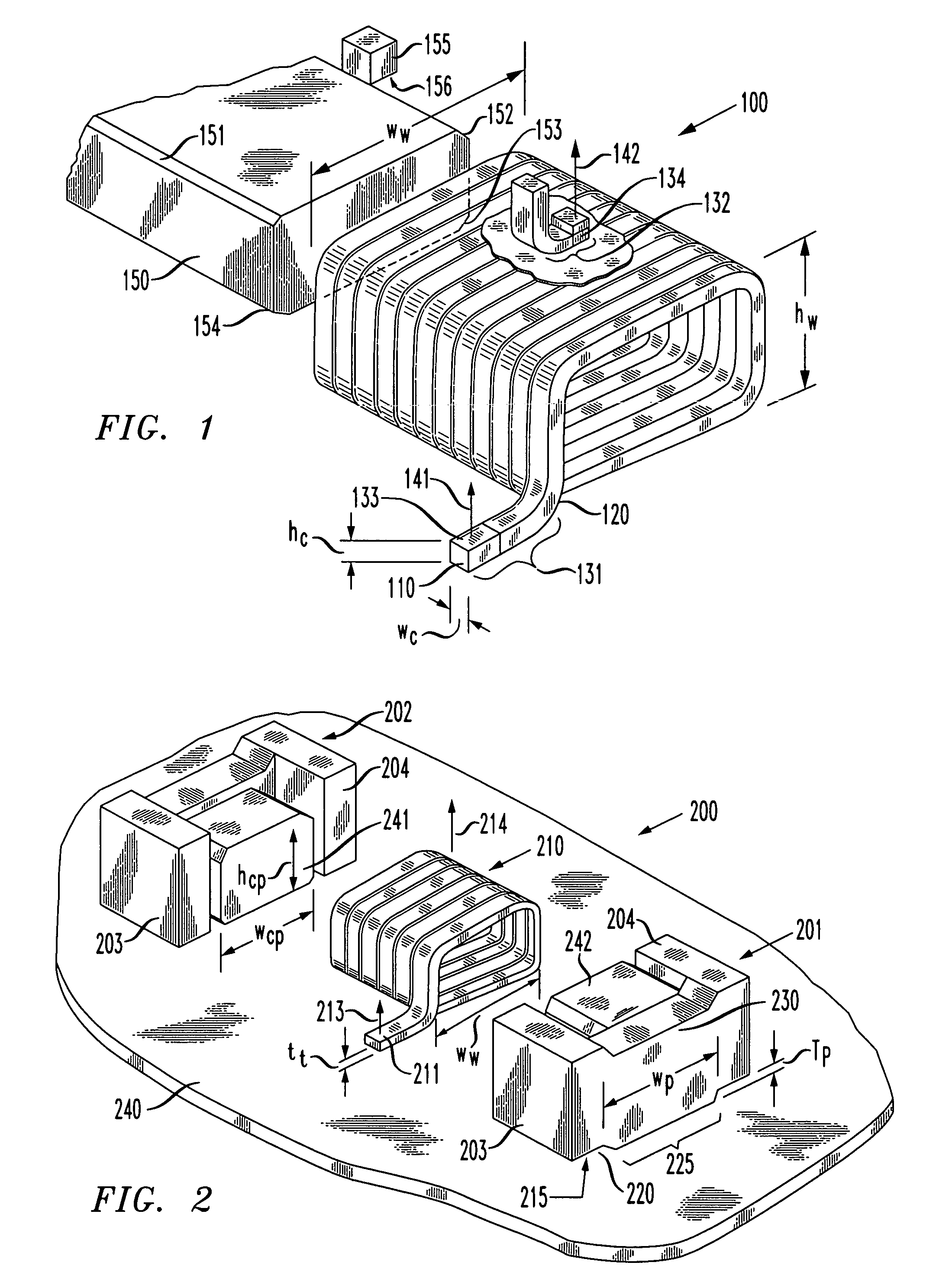
[0018]Referring initially to FIG. 1, illustrated is a top isometric view with partial cutaway of one embodiment of a springable winding 100 constructed according to the principles of the present invention. The springable winding 100 includes a substantially planar conductor 110 having a dielectric 120 thereabout. In one embodiment, substantially planar means that the conductor width wc is substantially larger than the conductor height hc. The substantially planar conductor 110 includes a conductive, springable material that has first and second termini 131, 132.

[0019]For the purposes of this discussion, a conductive springable material is any material that: (a) tends to recover its original shape when released after being distorted, and (b) is electrically conductive. For example, copper-clad, spring steel wire or copper and its alloys are suitable for this application. The springable material preferably has a spring constant ranging from about 750 to about 2000 grams / inch.

[0020]The...


PUM


Abstract

A magnetic device is provided that may be employed with surface mount technology. In an advantageous embodiment, the magnetic device includes a magnetic core having a magnetic core half and a springable winding positioned about at least a portion of the magnetic core half. The springable winding includes a terminus biased against the magnetic core half.

Description

TECHNICAL FIELD OF THE INVENTION[0001]The present invention is directed, in general, to magnetic devices and, more specifically, to a magnetic device having a springable winding and a method of manufacture thereof.BACKGROUND OF THE INVENTION[0002]Technological advancements in manufacturing have become essential as a seemingly endless array of consumer electronic devices continue to flood the commercial market. One of the most promising manufacturing improvements is with the introduction of surface mount technology using reflow furnaces and a conductive adhesive, typically solder. Surface mount technology is rapidly replacing through-hole assembly of printed circuit board because of speed of assembly and the ease of achieving a higher packing density.[0003]Depending upon the application, the marketplace today is continually demanding smaller, faster, lighter or increased power in these consumer electronic devices. Surface mount technology permits components to be mounted on both side...

Claims


Application Information

Patent Timeline
IPC IPC(8): H01F17/04H01F27/29H01F27/30
CPCH01F17/045H01F17/043H01F27/292H01F27/306
Inventor BUSLETTA, GALLIANO R.CATALANO, ROBERT J.OFFER, JR., PAUL J.ROESSLER, ROBERT J.WILKOWSKI, MATTHEW A.WOODS, WILLIAM L.
Owner ABB POWER ELECTRONICS INC
Why Eureka
Try Eureka