Resectoscope apparatus and electric operation apparatus

a technology of electric operation and electric probe, which is applied in the field of electric probe and electric probe, can solve the problem that the operator cannot perform the operation, and achieve the effect of improving the efficiency of the operation

Inactive Publication Date: 2005-08-16
OLYMPUS CORP
View PDF3 Cites 11 Cited by
  • Summary
  • Abstract
  • Description
  • Claims
  • Application Information

AI Technical Summary

Benefits of technology

[0013]A resectoscope apparatus comprises: a high-frequency power generating unit which generates high-frequency power for treating the anatomy; a first electrode which supplies to the anatomy, the high-frequency power generated by the high-frequency power generating unit; a solution supply unit which supplies a conductive solution around the electrode; and a second electrode which is arranged in the conductive solution supplied by the solution supply unit and which returns the high-frequency power supplied to the anatomy from the first electrode, wher...

Problems solved by technology

Thus, the patient body reflexively moves...

Method used


Image

  • Resectoscope apparatus and electric operation apparatus
  • Resectoscope apparatus and electric operation apparatus
  • Resectoscope apparatus and electric operation apparatus

Examples


first embodiment

[0049](First Embodiment)

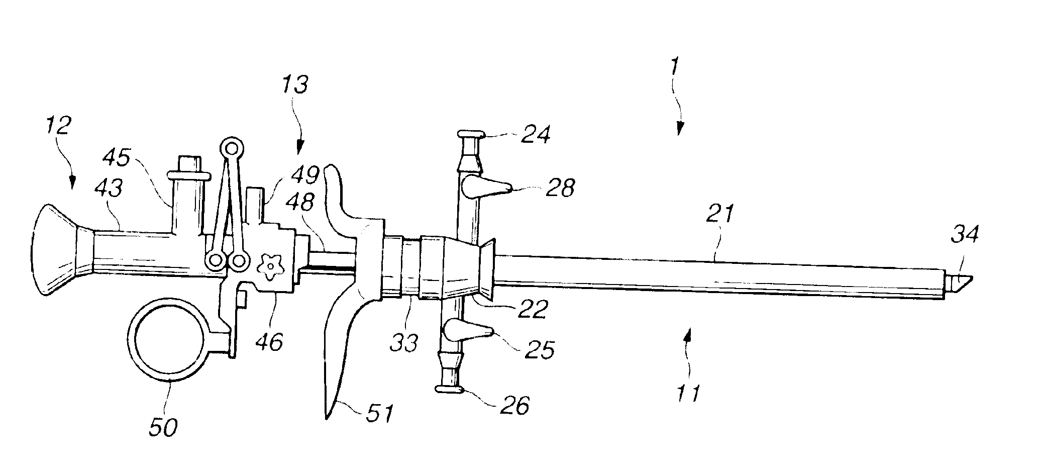
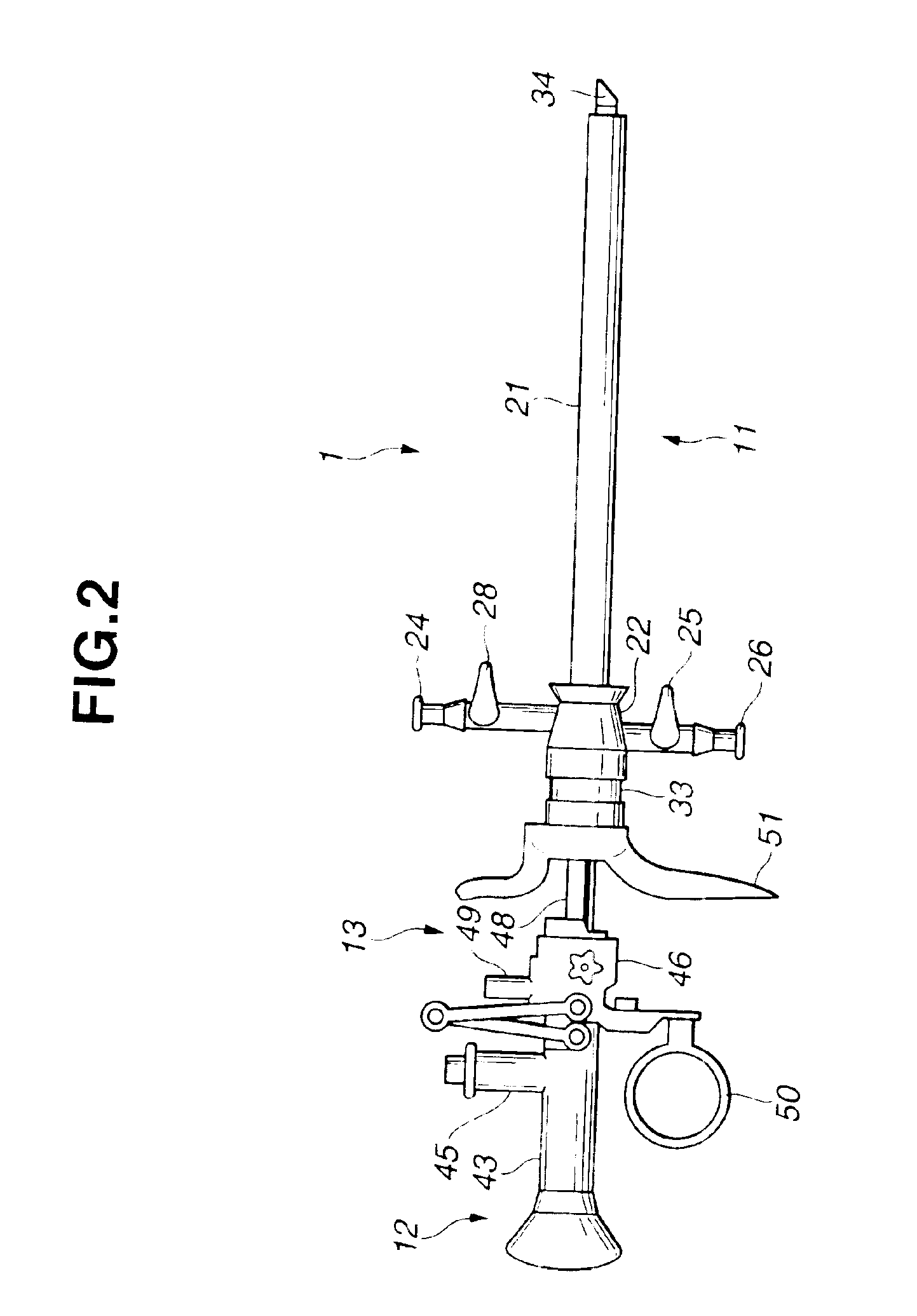
[0050]FIGS. 1 to 16 are diagrams according to a first embodiment of the present invention. FIG. 1 is a diagram showing the structure of a resectoscope apparatus, FIG. 2 is a side view showing the structure of a resectoscope shown in FIG. 1, FIG. 3 is an assembly diagram for explaining the structure of a resectoscope 1 shown in FIG. 2, FIG. 4 is a perspective view for explaining the structure of an electrode unit inserted and arranged in an inner sheath shown in FIG. 3, FIG. 5 is a block diagram showing the structure of a high-frequency power supply device shown in FIG. 1, FIG. 6 is a first diagram for explaining the operation of a treatment electrode shown in FIG. 4, FIG. 7 is a second diagram for explaining the operation of the treatment electrode shown in FIG. 4, FIG. 8 is a third diagram for explaining the operation of the treatment electrode shown in FIG. 4, FIG. 9 is a fourth diagram for explaining the operation of the treatment electrode shown in FIG. 4...

second embodiment

[0080](Second Embodiment)

[0081]FIG. 17 is a diagram for explaining the shape of an edge of a treatment electrode according to a second embodiment of the present invention.

[0082]The second embodiment is substantially the same as the first embodiment and therefore only different points are described and the same reference numeral denotes the same component.

[0083]Referring to FIG. 17, with respect to the treatment electrode 61 according to the second embodiment, a diameter φB of a semicircular bottom end portion is larger than a diameter φA of another portion and the bottom distal end portion is made thick. In other words, the diameter of the treatment electrode 61 is maximum at an intersection between the treatment electrode 61 and the second segment 152 vertical to the first segment 151 having the maximum distance between the intersection of the first segment 151 and the intersection of the treatment electrode 61.

[0084]In addition to the advantages according to the first embodiment, ...

third embodiment

[0087](Third Embodiment)

[0088]FIG. 18 is a diagram for explaining the structure of an electric operation apparatus using a resectoscope apparatus. The same reference numerals according to the first embodiment denote the same components.

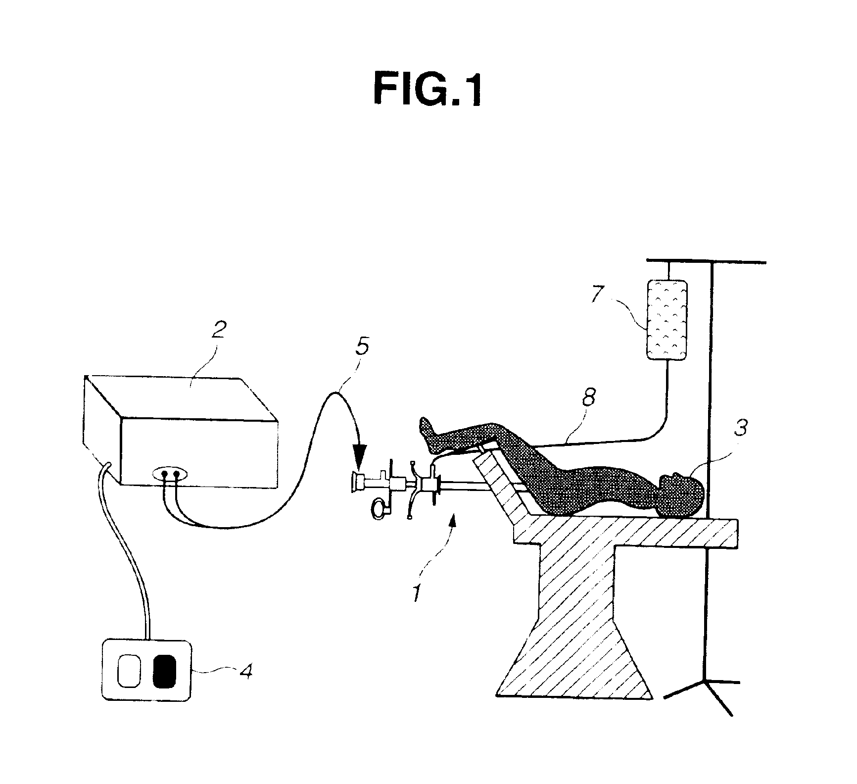
[0089]FIG. 18 shows a status for transurethral resection using the resectoscope apparatus. The resectoscope apparatus comprises the resectoscope 1 and the high-frequency power supply device 2. The resectoscope 1 is connected to the high-frequency power supply device 2 which supplies the high-frequency cautery current (hereinafter, referred to as active current) and which collects feedback current (hereinafter, referred to as return current), to / from the treatment electrode of the electrode unit which will be described later. The distal end portion of the resectoscope 1 is transurethrally inserted in the patient 3. The foot switch 4 connected to the high-frequency power supply device 2 is switched on or off to control the power supply to the treatment ...


PUM


Abstract

A treatment electrode of a resectoscope apparatus is substantially semicircular-shaped. A length a of a first segment and a length b of a second segment satisfy a relationship of (a>2·b). The first segment is in parallel with the plane on which a parallel lead member exists and has the maximum width of the treatment electrode. The second segment is vertical to the first segment and has the maximum distance between an intersection to the first segment and an intersection to the treatment electrode.

Description

[0001]This application claims benefits of Japanese Application No. 2002-112398 filed on Apr. 15, 2002, No. 2002-112393 filed on Apr. 15, 2002, and No. 2002-112394 filed on Apr. 15, 2002, the contents of which are incorporated by this reference.BACKGROUND OF THE INVENTION[0002]1. Field of the Invention[0003]The present invention relates to a resectoscope apparatus and an electric operation apparatus which incise, resect, and transpire the body tissue through electric resection under an endoscope.[0004]2. Description of the Related Art[0005]Generally, a resectoscope is used for transurethral resection (TUR) and transcervical resection (TCR), and mainly comprises an optical scope (also referred to as a scope) as an endoscope for observation and an electrode unit for resecting the anatomy in an elongated and hollow sheath inserted in the celom.[0006]The resectoscope apparatus includes two types of one for treatment in a non-conductive solution and one for treatment in a conductive solut...

Claims


Application Information

Patent Timeline
IPC IPC(8): A61B18/14
CPCA61B18/149A61B18/1815A61B2218/002
Inventor OHYAMA, MASAHIDEHIJII, KAZUYAHATTA, SHINJIHARANO, KENJINAKAMURA, TAKEAKIKIMURA, SHUICHI
Owner OLYMPUS CORP
Why Eureka
Try Eureka