Working instrument with handle element for use in a resectoscope, and handle element for a working instrument

a technology of working instruments and handle elements, which is applied in the direction of surgical instruments for heating, medical science, surgical forceps, etc., can solve the problems of not having particularly good handling features in the direction of working instruments to be held, risk of damaging the working instruments, etc., and achieve the effect of safe and effective force transmission and application

Inactive Publication Date: 2005-03-31
OLYMPUS WINTER & IBE
View PDF7 Cites 8 Cited by
  • Summary
  • Abstract
  • Description
  • Claims
  • Application Information

AI Technical Summary

Benefits of technology

[0019] The handle element, once it is separated from the working instrument, cannot be reconnected. This counteracts the risk of a working instrument designed for single use or a handle element designed for single use being used multiple times despite not being designed for multiple use.
[0020] Pushing forces applied to the handle element must be transmitted to the remainder of the working instrument. This could be facilitated, for example, by pushing the handle element on the support or working instrument up to an axial stop, although the handle element could also be connected by means of non-positive engagement to the support or working device. As a matter of principle, the transmission of force can be facilitated by any means. However, in a working instrument whose support comprises a guiding sleeve for guiding the electrode on a telescope of the resectoscope, it is advantageous for the handle element to be designed such as to transmit pushing forces to the guiding sleeve. The guiding sleeve is sufficiently stable to safely take up the applied forces.

Problems solved by technology

One problem associated with the type of assembly illustrated above is that the working instrument must be held with the fingers while it is being inserted through the bore in the main body and until it is locked in the sliding body.
However, neither of these areas possesses particularly good handling features, especially the distal end area of the working instrument which usually is not particularly resistant to the impact of forces applied to it.
Consequently, there is a risk of damaging the working instrument.
Moreover, there is a risk of injury if the working instrument bears a sharp-edged working device.
This means that the working instrument can no longer be guided through the internal sheath without damaging the cutting loop.
The handling problems described above are even more pronounced in this design.

Method used


Image

  • Working instrument with handle element for use in a resectoscope, and handle element for a working instrument
  • Working instrument with handle element for use in a resectoscope, and handle element for a working instrument
  • Working instrument with handle element for use in a resectoscope, and handle element for a working instrument

Examples


second embodiment

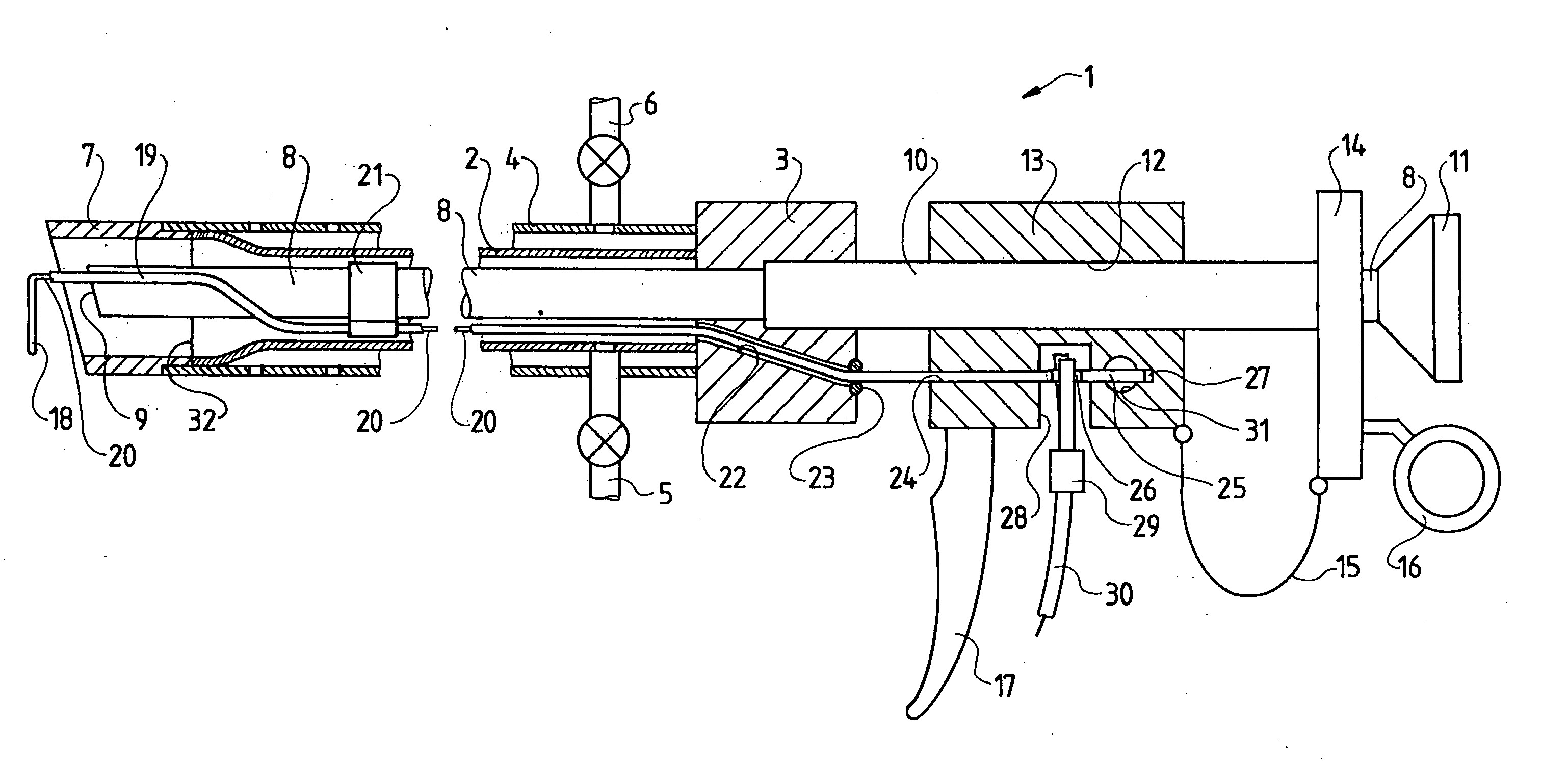
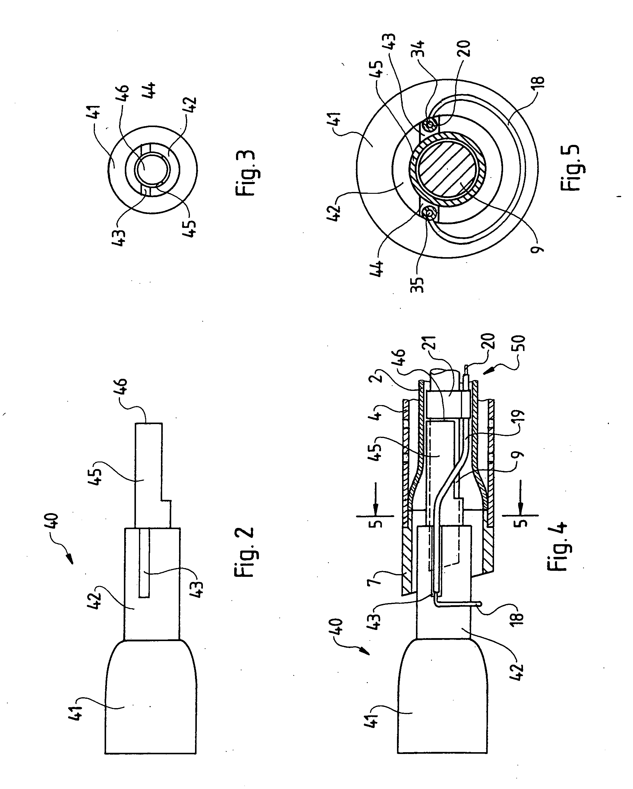
[0051] Following the insertion of the working instrument 50 into the resectoscope 1, the handle element 40 can be removed by simple pulling. However, the handle element 40 could also be firmly connected to the working instrument 50, e.g. by means of a glue connection between the tip area 45 and the forking site 47. In this case, the glue connection would have to be provided such that it is severed upon the application of a certain force, e.g. a pulling force. However, the separation should occur such that no fragments or sharp edges stay behind.

third embodiment

[0052] And finally, the handle element 40 of FIG. 7 shows a It is provided for a different working instrument 50, namely one with a cutting knife 36 as its working device. For this purpose, the tip area 45 of the handle element 40 is provided as a tube, the upper side of which comprises an axial slit 48, which receives the cutting knife 36 when the arrangement is pushed onto the working instrument 50. This form-fitting engagement between the handle element 40 and the working device 36 provides for the coupling of any rotation of the handle element 40 and working instrument 50. In addition, the internal diameter of the tube 45 can be selected such that the support 19 of the working instrument 50 is received in a clamping fashion. For this purpose, a narrow site can be provided for example. This provides for the handle element and the working instrument 50 to be connected to each other in a non-positive fashion in an axial direction also.

[0053] The handle element 40 of FIG. 7 can be ...


PUM


Abstract

A working instrument for use in a resectoscope with a pushing force-transmitting elongated support, whose proximal end area includes an attachment section for attachment in a resectoscope, and whose distal end area carries a working device. The working instrument includes, in its distal end area, a handle element. The handle element projects in a distal direction beyond the support and the working device and is connected to the working instrument so as to transmit pushing forces and can be removed.

Description

BACKGROUND OF THE INVENTION [0001] Working instruments of the type of the present invention are used in conjunction with resectoscopes, e.g. in urology or gynaecology. For this purpose, the working instruments are inserted into the resectoscope and then advanced through orifices and channels of the body, e.g. the urethra, to the desired treatment site, e.g. the prostate. [0002] Working instruments of this type consist of a long actuator rod, which can be attached in the sliding body of a resectoscope with their proximal end. On its distal end, the working instrument comprises a working device, e.g. a cutting loop to which a HF current can be applied, a cold knife, a curette or other devices known from the state-of-the-art, which allow the surgeon to perform the desired treatment, e.g. resection of the prostate, at the treatment site. [0003] Modern resectoscopes are provided as continuous irrigation resectoscopes, in which the continuous irrigation of the operative field provides a c...

Claims


Application Information

Patent Timeline
Patent Type & Authority Applications(United States)
IPC IPC(8): A61B1/018A61B1/307A61B17/00A61B17/28A61B17/32A61B18/14
CPCA61B17/2909A61B17/320016A61B18/14A61B2018/00178A61B2017/2924A61B2017/293A61B18/149A61B17/32
Inventor AUE, THOMASNUSSBAUM, FELIXWOSNITZA, THOMAS
Owner OLYMPUS WINTER & IBE
Why Eureka
Try Eureka