Solid-state image sensing apparatus with a relative positional light shift

a technology of image sensing and relative position, which is applied in the direction of color television details, television system details, television systems, etc., can solve the problems of deteriorating image quality and producing blurry photos, and achieve the effect of less blurry photos and high shutter speed

Inactive Publication Date: 2005-08-16
RAKUTEN GRP INC
View PDF9 Cites 12 Cited by
  • Summary
  • Abstract
  • Description
  • Claims
  • Application Information

AI Technical Summary

Benefits of technology

[0013]A purpose of the present invention is to provide an apparatus and a method of image sensing using a solid-state imaging device with a pixel-shifting function that achieve a high shutter speed with less blurry photos.

Problems solved by technology

Solid-state imaging apparatus with a pixel-shifting function having a large displacement of image “d” as discussed above produce blurry photos with a deteriorated image quality.

Method used


Image

  • Solid-state image sensing apparatus with a relative positional light shift
  • Solid-state image sensing apparatus with a relative positional light shift
  • Solid-state image sensing apparatus with a relative positional light shift

Examples


Embodiment Construction

[0023]Preferred embodiments according to the present invention will be disclosed with reference to the attached drawings.

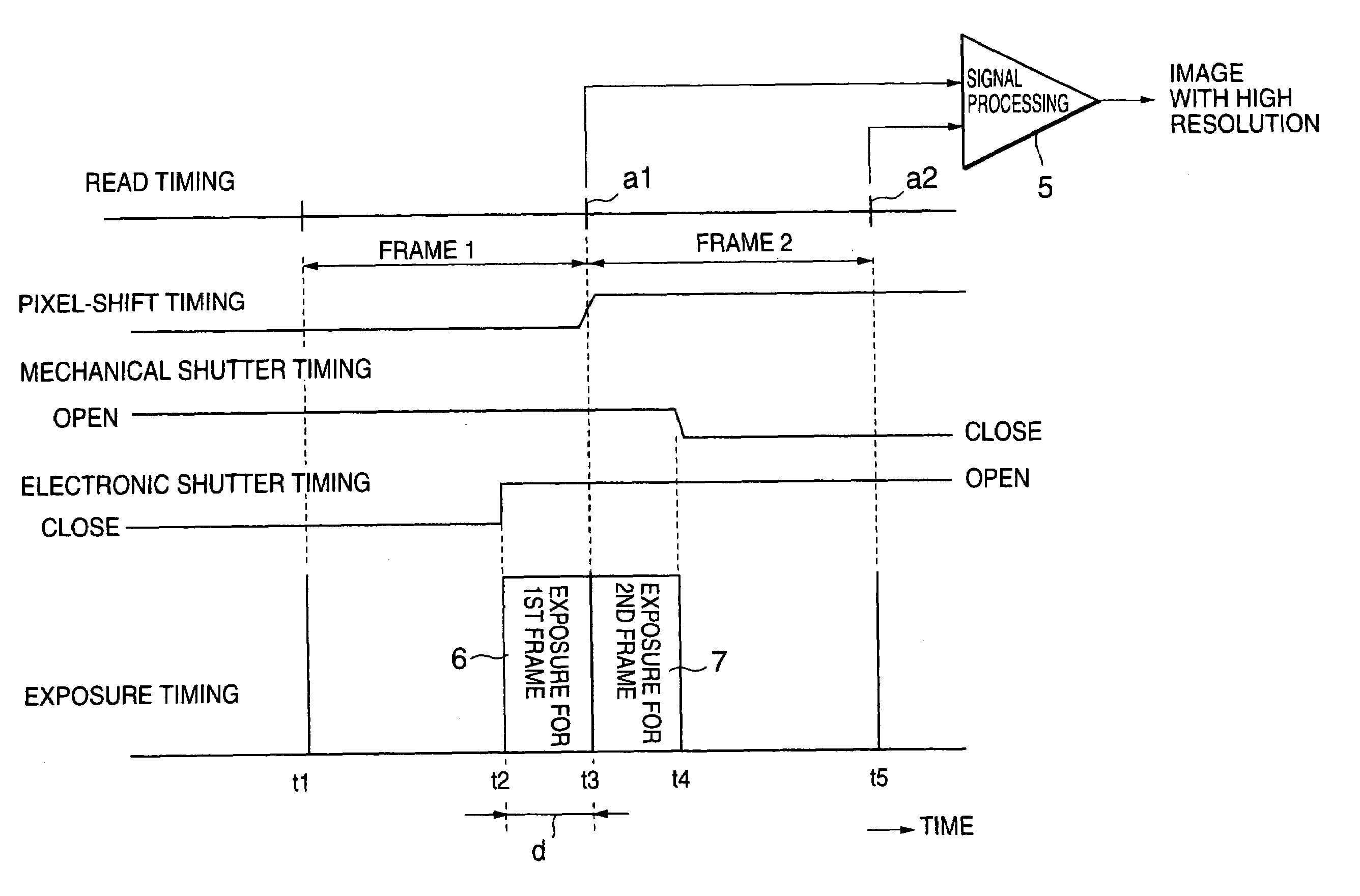
[0024]FIG. 3 shows a block diagram of a preferred embodiment of a solid-state image sensing apparatus according to the present invention.

[0025]Light from an object (not shown) is incident to a shutter mechanism 11 through a lens mechanism 10. The shutter mechanism 11 (one of the important elements of this invention) is a mechanical shutter operated by a user via a shutter release button 14.

[0026]The light that has passed through the shutter mechanism 11 is further incident to an imaging circuit 13 through a pixel-shift mechanism 12. The imaging circuit 13 is provided with a CCD, a vertical transfer resister and a horizontal transfer resister.

[0027]The light incident to the imaging circuit 13 is converted into an image signal by photo-to-electric conversion under the control by a timing signal fed by a timing signal generator (TG) 18. The image signal is supplied t...


PUM


Abstract

Light from an object is incident to an image sensing device and converted into an image signal. The image sensing device is exposed to the light by a shutter, provided between the object and the solid-state image sensing device, for a first exposure period and a second exposure period that directly follows the first exposure period. The first and the second periods are the same length in time. Each exposure period for exposing the solid-state image sensing device to the light corresponds to one frame or one filed of the object. A passage of the light that has passed the shutter and incident to the solid-state image sensing device is shifted in a predetermined direction with respect to the solid-state image sensing device at least in the second exposure period. Image signals converted for the first and the second exposure periods are combined to generate a composite image signal.

Description

BACKGROUND OF THE INVENTION[0001]The present invention relates to image sensing using a solid-state image sensing apparatus. Particularly, this invention relates to image sensing using a solid-state image sensing apparatus with a function of shifting light from an object to shift pixels for enhancing resolution equivalent to the resolution of a solid-state image sensing apparatus having a larger number of pixels.[0002]Video cameras with a digital still-photographing function and digital still cameras install a solid-state image sensing apparatus with a function of shifting light incident to a solid-state image sensing device from an object to shift pixels for enhancing resolution equivalent to the resolution of a solid-state image sensing apparatus having a larger number of pixels (called a pixel-shifting function hereinafter).[0003]Illustrated in FIG. 1 is a timing chart of exposure and reading for a solid-state image sensing device with such a pixel-shifting function. As illustrat...

Claims


Application Information

Patent Timeline
Patent Type & Authority Patents(United States)
IPC IPC(8): H04N3/14H04N5/238H04N5/335H04N5/232H04N5/262H04N5/225H04N5/349H04N5/351H04N5/353H04N5/372
CPCH04N5/23248H04N5/23287H04N5/2329H04N5/262H04N5/335H04N23/68H04N23/689H04N23/687H04N25/00
Inventor TENGEIJI, HIDEKIENDO, TOSHIYAOTAKE, YOSHICHI
Owner RAKUTEN GRP INC
Why Eureka
Try Eureka