
Appearance inspection apparatus

a technology of appearance inspection and apparatus, which is applied in the field of appearance inspection apparatus, can solve the problem of not being able to obtain a high shutter speed, and achieve the effects of high resolution, fast data processing in the shape judging section, and increased shutter speed of the area sensor camera

Active Publication Date: 2014-08-05
DAIICHI JITSUGYO VISWILL
View PDF19 Cites 1 Cited by
  • Summary
  • Abstract
  • Description
  • Claims
  • Application Information

AI Technical Summary

Benefits of technology

The present invention is a three-dimensional appearance inspection apparatus that uses a light-section method. It allows for an increase in the shutter speed of an area sensor camera, resulting in highly accurate inspection. The apparatus captures two images simultaneously and outputs them simultaneously, reducing the output time to half compared to conventional apparatus. This enables the camera to achieve a higher shutter speed. The two images should have the same top-bottom orientation to avoid the need for shape reversal processing. The mirrors in the optical mechanisms should receive reflected lights with the same elevation angle to avoid height information correction. The angles of the reflective surfaces of the mirrors should be adjusted to align the vertical positions of the images and facilitate quick and accurate inspection. The reduced time of outputting two image data results in higher resolution image data and more accurate appearance inspection.

Problems solved by technology

However, the above conventional appearance inspection apparatus has the following problem.
Therefore, it is not possible to obtain a high shutter speed which is necessary for performing highly accurate inspection.

Method used


Image

  • Appearance inspection apparatus
  • Appearance inspection apparatus
  • Appearance inspection apparatus

Examples


Embodiment Construction

[0056]Hereinafter, one specific embodiment of the present disclosure will be described on the basis of the drawings.

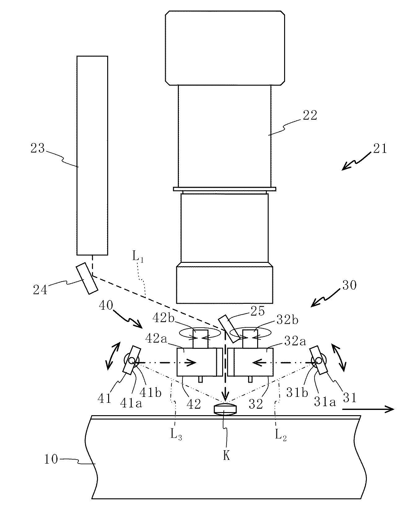
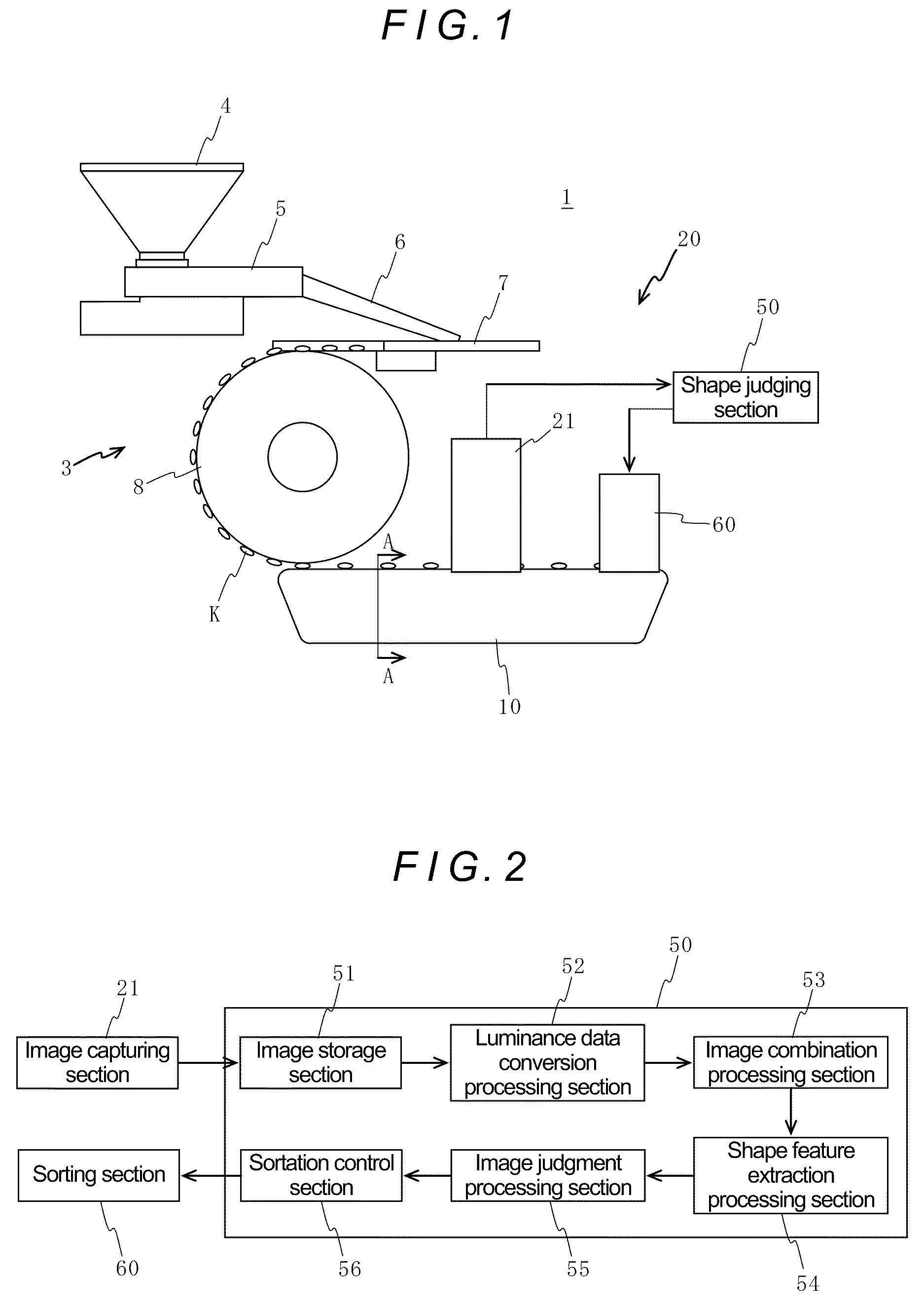
[0057]As shown in FIG. 1, an appearance inspection apparatus 1 of the embodiment has a supply section 3 for aligning inspection objects K and supplying them, a straight conveying section 10 for straight conveyance of the supplied inspection objects K, and a surface shape inspecting section 20 for inspecting the surface shape of each of the inspection objects K being conveyed and sorting them.

[0058]As examples of the inspection object K in the embodiment, there can be mentioned a medicine (tablet, capsule etc.), a food product, a machine component, an electronic component and the like. However, the inspection object K is not limited thereto.

[0059]Hereinafter, each of the above-mentioned sections will be explained in detail.

Supply Section

[0060]The supply section 3 comprises a hopper 4 into which a large number of inspection objects K are thrown, a vibrating feeder 5 whic...


PUM


Abstract

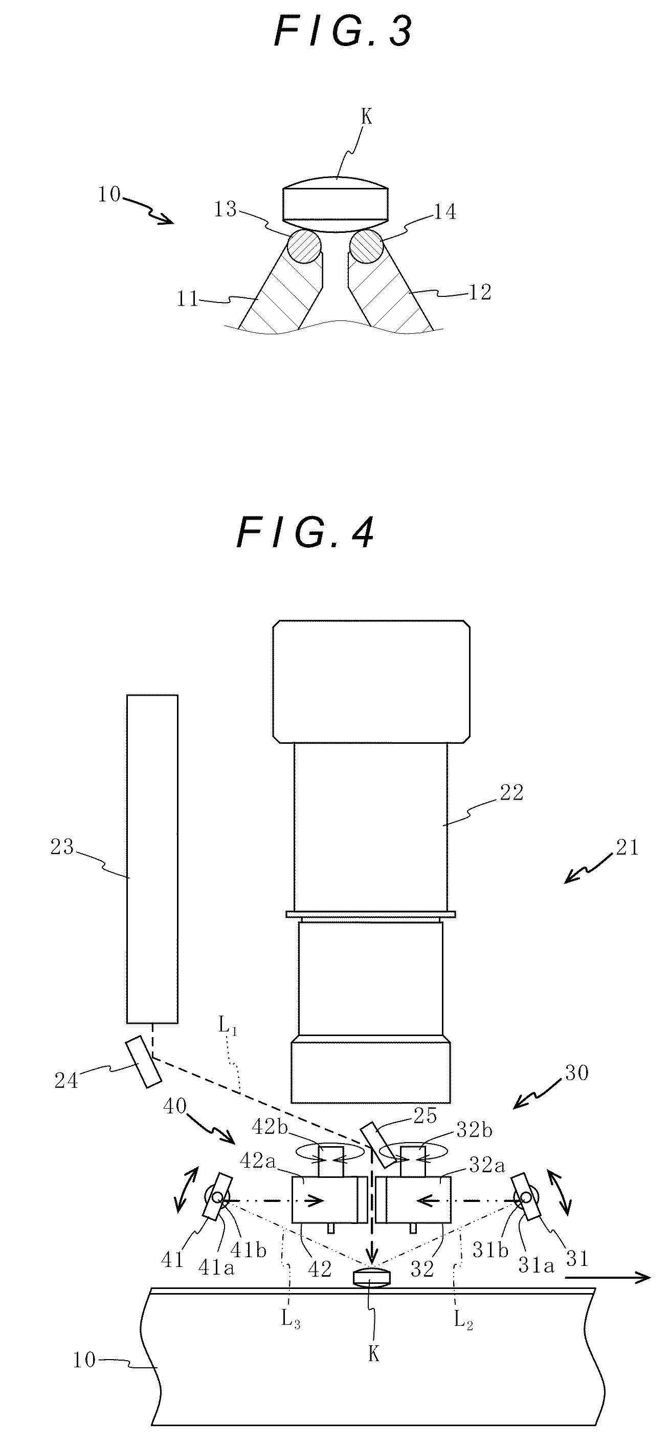
An appearance inspection apparatus has conveying means for conveying an inspection object and surface shape inspecting means for inspecting the surface shape of the inspection object. The surface shape inspection means has a slit beam irradiating section for irradiating a band-shaped slit beam on the surface of the inspection object, an area sensor camera for capturing images of the slit beam, first and second optical mechanisms for receiving reflected lights of the slit beam on the downstream and upstream sides in a conveyance direction, respectively, and guiding them to the area sensor camera, and a shape judging section for judging appropriateness of the surface of the inspection object based on images captured by the area sensor camera. Optical paths of the first and second optical mechanisms allow images of the reflected lights to be formed on the area sensor camera in a state of being aligned laterally.

Description

FIELD OF THE DISCLOSURE[0001]The present disclosure relates to an apparatus for inspecting the appearance of a medicine (tablet, capsule etc.), a food product, a machine component, an electronic component or the like (hereinafter, referred to as an “inspection object”).BACKGROUND OF THE DISCLOSURE[0002]Conventionally, as an apparatus for inspecting the appearance of the surface of an inspection object as mentioned above, the apparatus disclosed in the Japanese Unexamined Patent Application Publication No. 2004-317126 is known, for example.[0003]In this apparatus, a laser slit beam is irradiated on the surface of an inspection object, the irradiated laser slit beam is imaged by an appropriate imaging device, and information on the height of the surface of the inspection object is obtained by analyzing the obtained image according to a light-section method. On the basis of the obtained height information, flaws, chips and the like which are present in the surface of the inspection obj...

Claims


Application Information

Patent Timeline
Patent Type & Authority Patents(United States)
IPC IPC(8): H04N7/18
CPCG01B11/2545G01N21/8806G01N21/9508B07C5/00G01B11/24G01N21/88
Inventor MATSUDA, SHINYAAOKI, HIROSHIONOE, TOSHIAKI
Owner DAIICHI JITSUGYO VISWILL
Learn More