
Scan conversion apparatus

a conversion apparatus and scanning technology, applied in the direction of signal generators with optical-mechanical scanning, picture reproducers using projection devices, television systems, etc., can solve the problems of significant deformation of display quality, inefficient use of available information, and reduced screen spatial resolution, so as to achieve the effect of smoother slanting lines of images

Inactive Publication Date: 2005-08-16
LG ELECTRONICS INC
View PDF27 Cites 17 Cited by
  • Summary
  • Abstract
  • Description
  • Claims
  • Application Information

AI Technical Summary

Benefits of technology

[0018]In another aspect of the present invention, a method for converting image signals from an interlaced scanning format to a progressive scanning format includes: estimating field motions between a current field and reference fields, the reference fields being prior or next to the current field; restoring a missing line of the current field using information given from an optimal reference field if the optimal reference field unevenly matches to the current field, the optimal reference field being one of the reference fields having the shortest distance to the current field; restoring the missing line of the current field by linearly interpolating lines located adjacent to the missing line in the current field if the optimal reference field evenly matches to the current field; making smoother slanting lines of an image of the image signals by using an edge-preserving filter; and storing the current field and the reference fields in a field buffer.
[0019]In another aspect of the present invention, a method for changing a vertical scanning rate of progressively scanned image signals includes the following: estimating field motions between a current field and reference fields, said reference fields being prior to or next to the current field; restoring a missing line of the current field using information given from an optimal reference field if the optimal reference field unevenly matches to the current field, the optimal reference field being one of the reference fields having the shortest distance to the current field; estimating frame motions between adjacent frames using the progressively scanned image signals and the estimated field motions; proving a new composite image between the adjacent frames using the frame motions estimated; restoring the missing line of the current field by linearly interpolating lines located adjacent to the missing if the optimal reference field evenly matches to the current field; making smoother slanting lines of an image of the image signals using an edge-preserving filter; storing the current field and the reference fields in a field buffer; and storing the progressively scanned image signals in a frame buffer.

Problems solved by technology

However, even if there is any very small amount of the movement in the image, the pixel values must be obtained only from information given from the current field, causing inefficient uses of available information, and the spatial resolution of the screen is reduced so that the display quality is significantly degraded.
As a matter of fact, moving image data are constantly changing, but we can only presume that adjacent picture frames have high correlations to each other, and the levels of such movements are quite insignificant.
Otherwise, the cumulative error will be increased significantly.

Method used


Image

  • Scan conversion apparatus
  • Scan conversion apparatus
  • Scan conversion apparatus

Examples


Embodiment Construction

[0030]Reference will now be made in detail to the preferred embodiments of the present invention, examples of which are illustrated in the accompanying drawings.

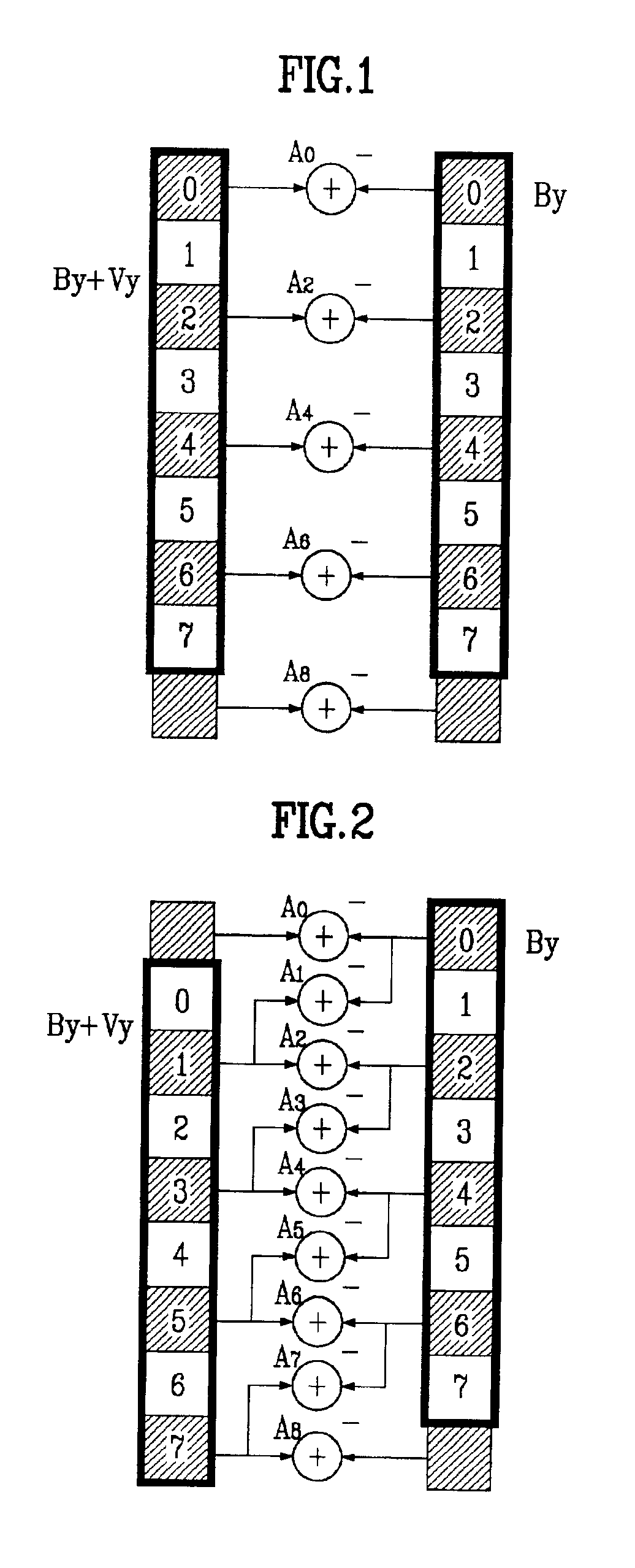
[0031]Generally, in order to estimate the motion between two frames, an image is first divided into several sub-images, and then the motion of each divided sub-image is estimated. Correlations between a current sub-image (a sub-image in a current field) and sub-images of the reference fields spatially located close to the current field are initially evaluated, and the optimal sub-image of reference field that has the shortest distance from the current sub-image is determined.

[0032]Although the size of each sub-image is normally variable depending upon the size of the entire image or the volume of calculations, a size of 16 by 16 is typically used. However, this size is usually appropriate for an encoding process, but rather a smaller size is desired for handling interpolations or compensations of motions. A size of 8 by 8 is...


PUM


Abstract

An apparatus and a method for converting image signals from an interlaced scanning format to a progressive scanning format are disclosed. Additionally, an apparatus and a method for changing a vertical scanning rate of progressively scanned image signals are also disclosed. Field motion estimator estimates field motions between a current field and reference fields to find an optimal reference field. Then a field motion compensator restores a missing line of the current field using information given from the optimal reference if the optimal reference field unevenly matches to the current field. Otherwise, a linear interpolator restores the missing line of the current field by linearly interpolating lines located adjacent to the missing line in the current field. Furthermore, a frame motion estimator estimates frame motions between adjacent frames using the progressively scanned image signals and field motions estimated in the field motions estimator. Finally, a frame motion compensator provides a new composite image between the adjacent frames using the frame motions estimated.

Description

CROSS REFERENCE TO RELATED ART[0001]This application claims the benefit of Korean Patent Application No. 2000-34561, filed on Jun. 22, 2000, which is hereby incorporated by reference in its entirety.BACKGROUND OF THE INVENTION[0002]1. Field of the Invention[0003]The present invention relates to converting the format of image signals from an interlaced scanning to a progressive scanning, and more particularly, to an apparatus and a method for converting to a progressive scanning format which restores the line data missing from each field of an image by analyzing motions of corresponding reference fields of the image.[0004]2. Background of the Related Art[0005]Recently, digital image devices such as digital televisions and DVDs became so popular so that they now coexist with analog image devices such as conventional television systems. Therefore, it is necessary to display analog signals on the digital devices. Generally, the analog TV image signals have an interlaced scanning format,...

Claims


Application Information

Patent Timeline
IPC IPC(8): H04N5/44H04N5/46
CPCH04N7/012H04N5/46
Inventor RHEE, SEUNG HYEON
Owner LG ELECTRONICS INC
Learn More