Multi-leaf collimator and medical system including accelerator

a collimator and multi-leaf technology, applied in the field of multi-leaf collimators, can solve problems such as physical and mental burdens on patients, adversely affecting the normal part, and difficulties in shortening the remedy tim

Inactive Publication Date: 2005-08-16
HITACHI LTD
View PDF6 Cites 155 Cited by
  • Summary
  • Abstract
  • Description
  • Claims
  • Application Information

AI Technical Summary

Benefits of technology

[0012]Accordingly, it is an object of the present invention to provide a multi-leaf collimator and a medical system including an accelerator, which can shorten a positioning time required for forming an irradiation field with high accuracy by using a number of leaf plates, and can reduce physical and mental burdens imposed on patients.
[0015]Thus, the present invention enables the leaf plates to be successively positioned in each of the leaf plate driving body while moving a plurality of leaf plates at the same time. Therefore, when the irradiation field is formed with high accuracy, a time required for completing the formation of the irradiation field can be shortened in comparison with a conventional structure wherein a number of leaf plates must be positioned one by one successively in each leaf plate driver. As a result, physical and mental burdens imposed on patients can be reduced.

Problems solved by technology

Irradiation of the radiation beam, which has been emitted for remedy of the diseased part, to the normal part around the diseased part may adversely affect the normal part.
This results in difficulties in shortening a remedy time, and hence in reducing physical and mental burdens imposed on patients.

Method used


Image

  • Multi-leaf collimator and medical system including accelerator
  • Multi-leaf collimator and medical system including accelerator
  • Multi-leaf collimator and medical system including accelerator

Examples


first embodiment

[0037]the present invention will be described with reference to FIGS. 1 to 9.

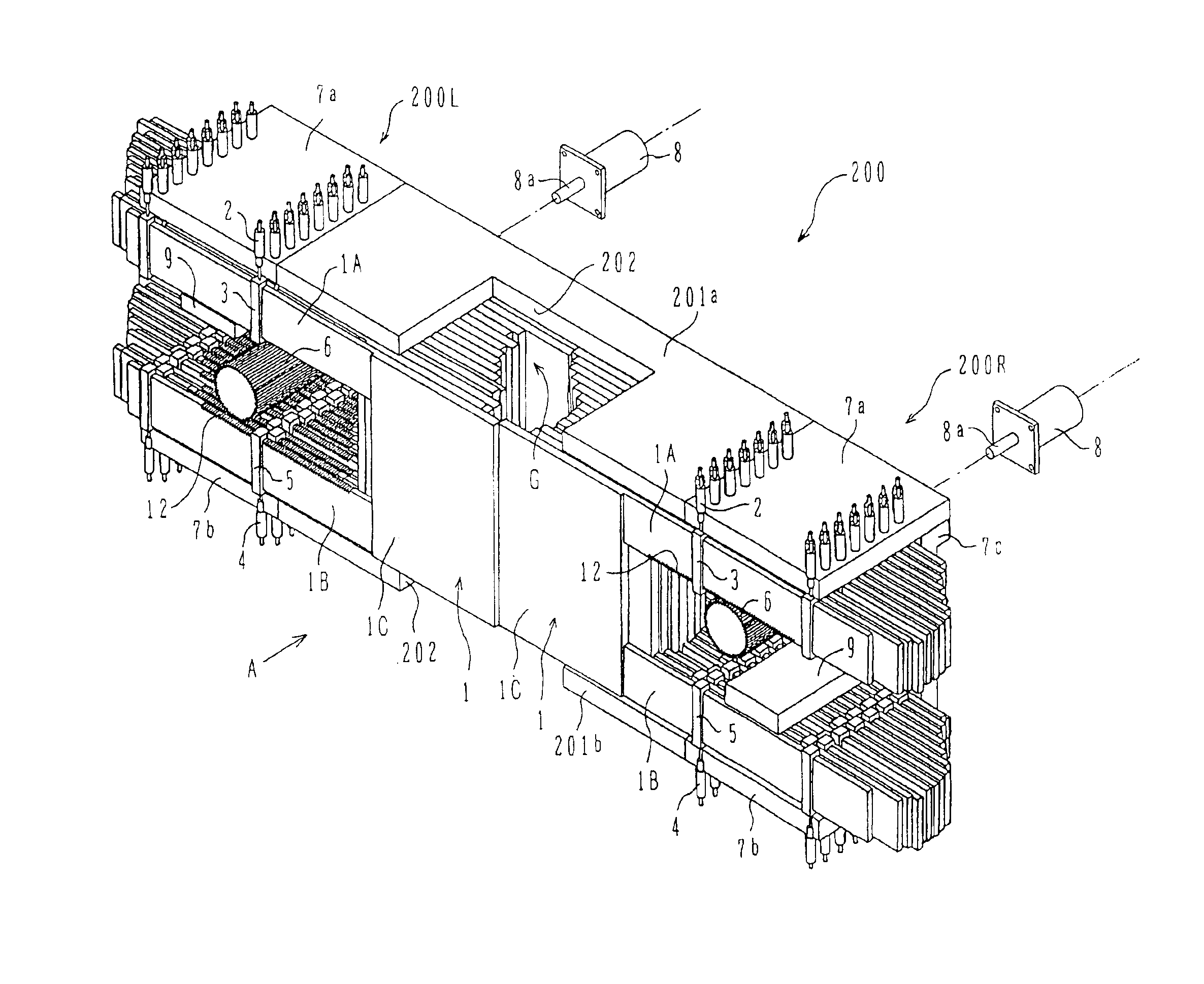
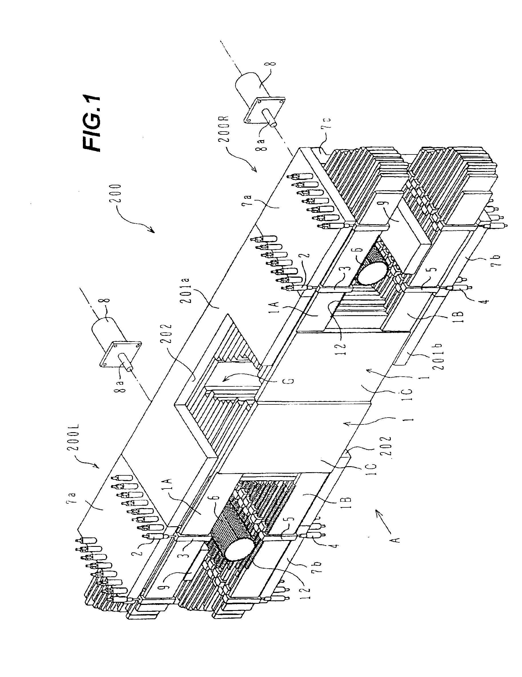
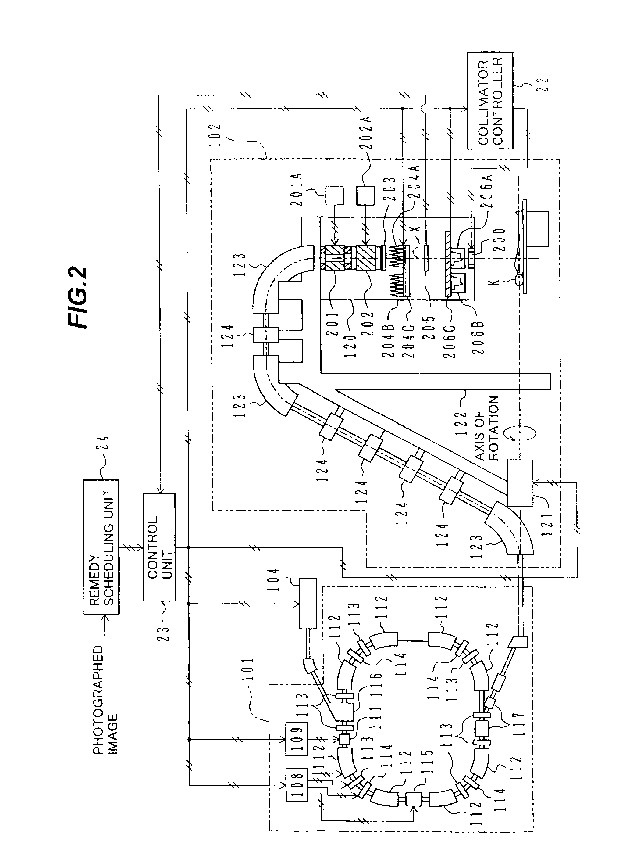
[0038]FIG. 2 is a conceptual block diagram showing an overall system configuration of a medical system including a radiation beam irradiator comprising a multi-leaf collimator of this embodiment and an accelerator.

[0039]In the radiation beam irradiator, a radiation beam (also referred to simply as a “beam” hereinafter), such as a charged particle beam, accelerated by an accelerator (synchrotron) 101 is outputted from a rotating irradiator 102 under control of a control unit 23 for irradiation to the diseased part of a patient K. By turning the rotating irradiator 102 about an axis of the rotation, the beam can be irradiated to the diseased part from a plurality of directions.

(1) Outline and Operation of Synchrotron 101

[0040]The synchrotron 101 comprises a high-frequency applying apparatus 111 for applying a high-frequency magnetic field and electric field (referred to together as a “high-frequency electroma...


PUM


Abstract

The invention is intended to shorten a positioning time required for forming an irradiation area with high accuracy using a number of leaf plates, and to reduce physical and mental burdens imposed on patients. A multi-leaf collimator comprises leaf plate driving body each including a plurality of movable leaf plates and provided respectively on one side and the other side, the plurality of leaf plates of the leaf plate driver on one side and the plurality of leaf plates of the leaf plate driver on the other side being disposed in an opposing relation to form an irradiation field of a radiation beam between the opposing leaf plates. Each of the leaf plate driving body includes a motor provided in common to the plurality of leaf plates. Driving force of the motor can be transmitted to the plurality of leaf plates at the same time through a pinion gear, upper and lower air cylinders, and upper and lower guides. Also, the driving force can be cut off selectively for each leaf plate.

Description

[0001]This application is a continuation of application Ser. No. 10 / 676,059, filed Oct. 2, 2003 now U.S. Pat. No. 6,823,045, which is a continuation of application Ser. No. 09 / 943,385, filed Aug. 31, 2001, now U.S. Pat. No. 6,792,078. This application is related to application Ser. No. 10 / 676,063, filed Oct. 2, 2003.BACKGROUND AND SUMMARY OF THE INVENTION[0002]1. Field of the Invention[0003]The present invention relates to a multi-leaf collimator for, when a radiation beam is irradiated to a target inside a radiation object, forming an irradiation area of the radiation beam in match with a target shape. The present invention also relates to a medical system including an accelerator.[0004]2. Description of the Related Art[0005]In one typical example for irradiating a radiation beam (e.g., a charged particle beam) to a target inside a radiation object, the radiation beam is irradiated to cancer cells (referred to as “diseased part” hereinafter) in a patient body. In such a case, the r...

Claims


Application Information

Patent Timeline
Patent Type & Authority Patents(United States)
IPC IPC(8): G21K1/04G21K1/02A61N5/10
CPCA61N5/1042G21K1/04G21K1/046
Inventor KATO, KOHEIAKIYAMA, HIROSHIYANAGISAWA, MASAKI
Owner HITACHI LTD
Why Eureka
Try Eureka